Voltage regulator

a voltage regulator and transient response technology, applied in the direction of electric variable regulation, process and machine control, instruments, etc., can solve the problems of deteriorating transient response characteristic of voltage regulators and the inability to reduce consumption, so as to improve the transient response characteristic, reduce the time constant, and the effect of curren

Active Publication Date: 2012-10-09
ABLIC INC
View PDF8 Cites 6 Cited by
  • Summary
  • Abstract
  • Description
  • Claims
  • Application Information

AI Technical Summary

Benefits of technology

[0009]The present invention has an object to provide a voltage regulator that is excellent in transient response characteristic even when a resistance value of a phase compensation resistor is large, and is relatively low in current consumption during normal operation.
[0011]In the present invention, the fluctuating output voltage is detected without increasing the current consumption of the differential amplifier, and the phase compensation resistor is temporarily short-circuited, to thereby decrease a time constant determined by a parasitic capacitance of the output transistor and the phase compensation resistor to improve the transient response characteristic. Alternatively, the voltage divider circuit is short-circuited to temporarily increase the current consumption and correct the output voltage, with the result that the current consumption during the normal operation is relatively low, and a transient response is improved by increasing a current only during the transient response.

Problems solved by technology

Therefore, the current consumption may not be reduced in the related art voltage regulator.
That is, there arises such a problem that the transient response characteristic is deteriorated by the phase compensation circuit 61, and the transient response characteristic of the voltage regulator is deteriorated.

Method used


Image

  • Voltage regulator
  • Voltage regulator
  • Voltage regulator

Examples


first embodiment

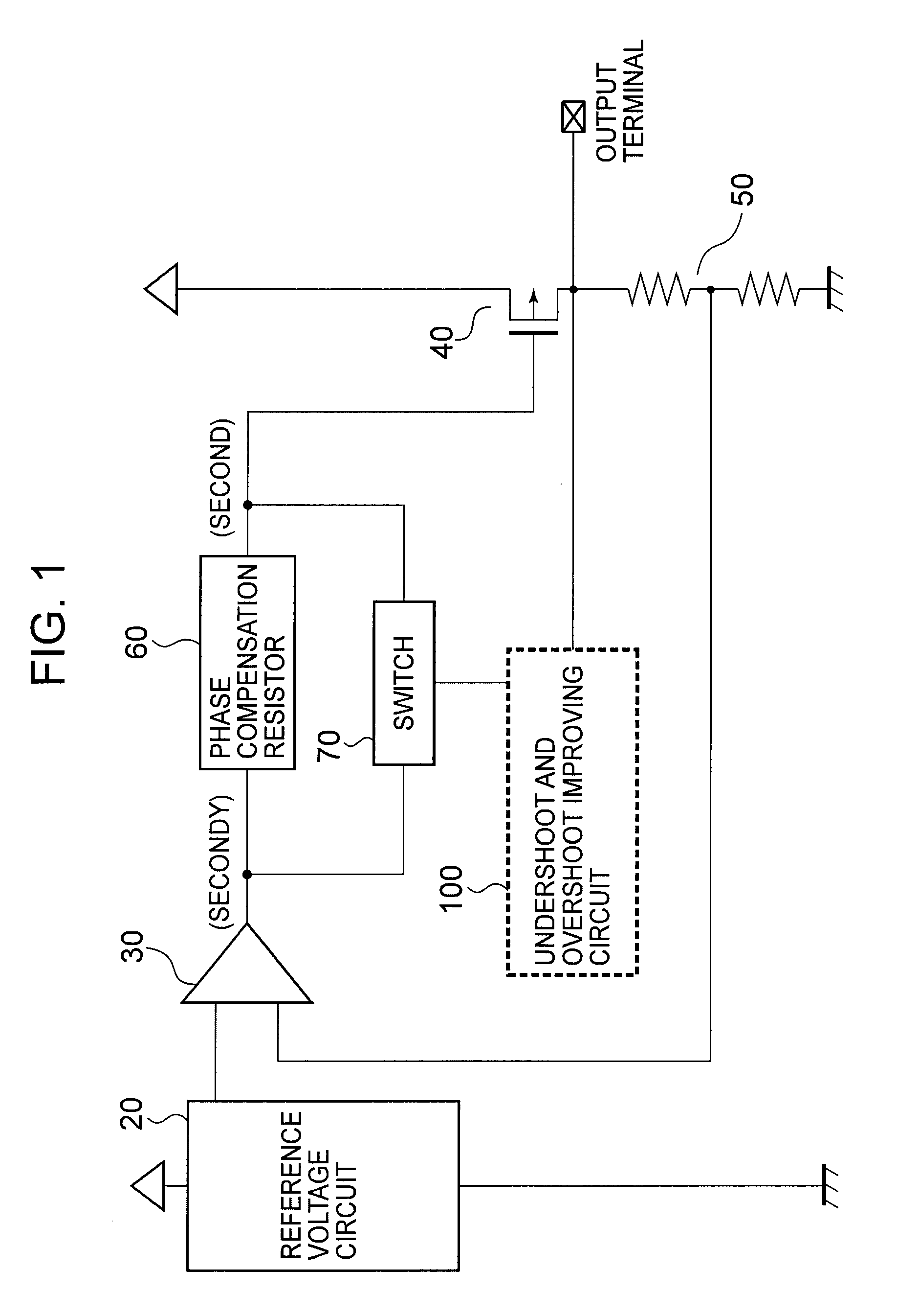
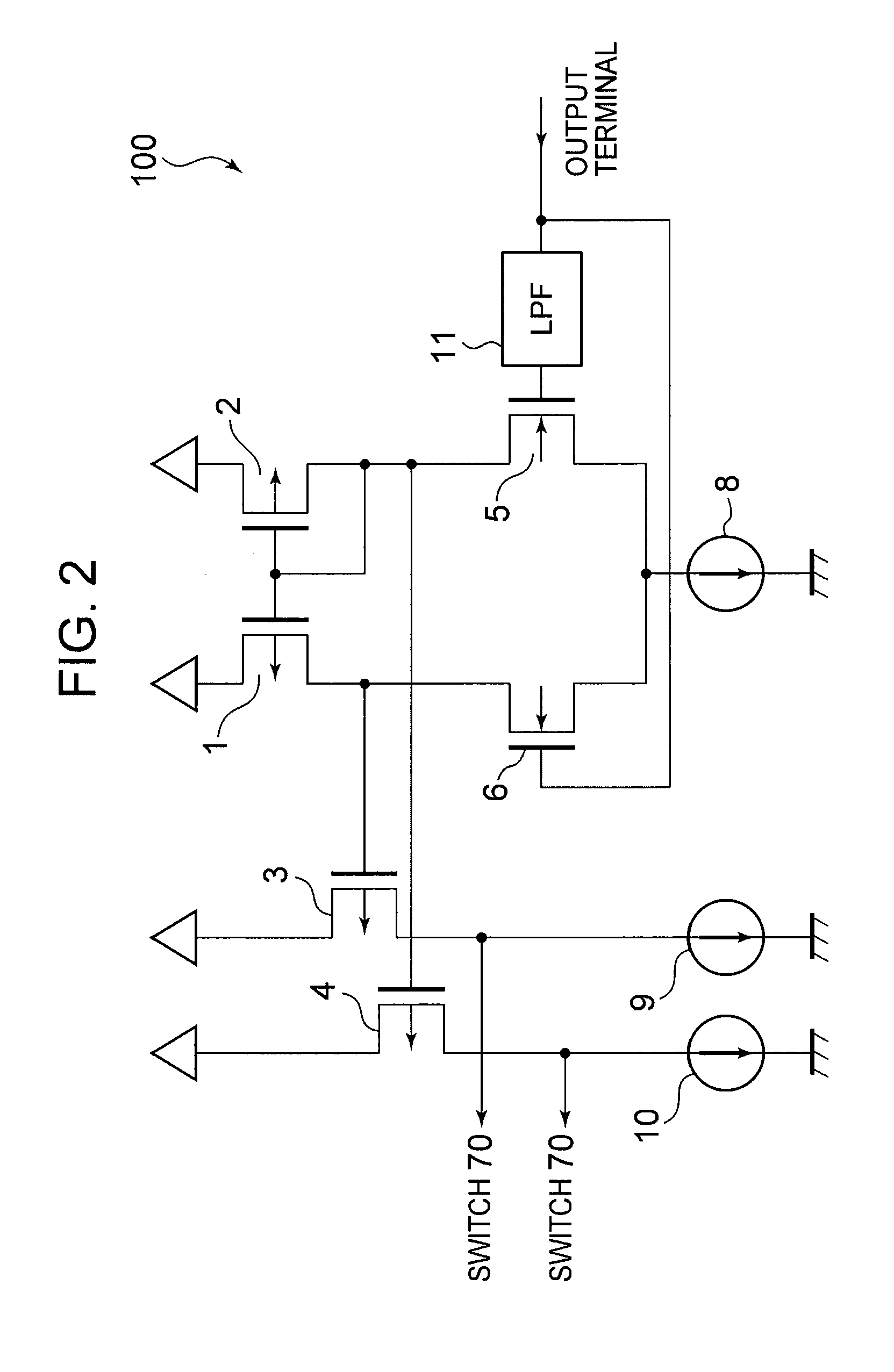
[0025]FIG. 1 illustrates a voltage regulator according to a first embodiment. FIG. 2 illustrates an undershoot and overshoot improving circuit 100. The undershoot and overshoot improving circuit 100 is configured to detect a fluctuation of an output voltage, and operates so as to reduce the fluctuation. Hereinafter, the configuration and operation of the undershoot and overshoot improving circuit 100 are described.

[0026]The voltage regulator includes a reference voltage circuit 20, a differential amplifier 30, an output transistor 40, a voltage divider circuit 50, a phase compensation resistor 60, a switch 70 that short-circuits the phase compensation resistor 60, and the undershoot and overshoot improving circuit 100. The undershoot and overshoot improving circuit 100 includes PMOS transistors (PMOS) 1 to 4, NMOS transistors (NMOS) 5 and 6, constant current circuits 8 to 10, and a low-pass filter (LPF) 11.

[0027]The output transistor 40 has a gate connected to an output terminal of ...

second embodiment

[0038]FIG. 3 illustrates a voltage regulator according to a second embodiment. FIG. 4 illustrates an overshoot improving circuit 90. FIG. 8 illustrates a switch 80. The reference voltage circuit 20, the differential amplifier 30, the output transistor 40, the voltage divider circuit 50, and the phase compensation resistor 60 are identical with those in the first embodiment. A difference from the first embodiment resides in that the switch 70 and the undershoot and overshoot improving circuit 100 are removed from the voltage regulator, and the switch 80 and the overshoot improving circuit 90 are inserted into the voltage regulator.

[0039]The overshoot improving circuit 90 includes PMOSs 1 to 3, NMOSs 5 and 6, constant current circuits 8 and 9, and an LPF 11. The switch 80 includes an NMOS 7.

[0040]The overshoot improving circuit 90 is connected to the output terminal of the voltage regulator, and detects an AC component of the output voltage when the output voltage fluctuates, to there...

third embodiment

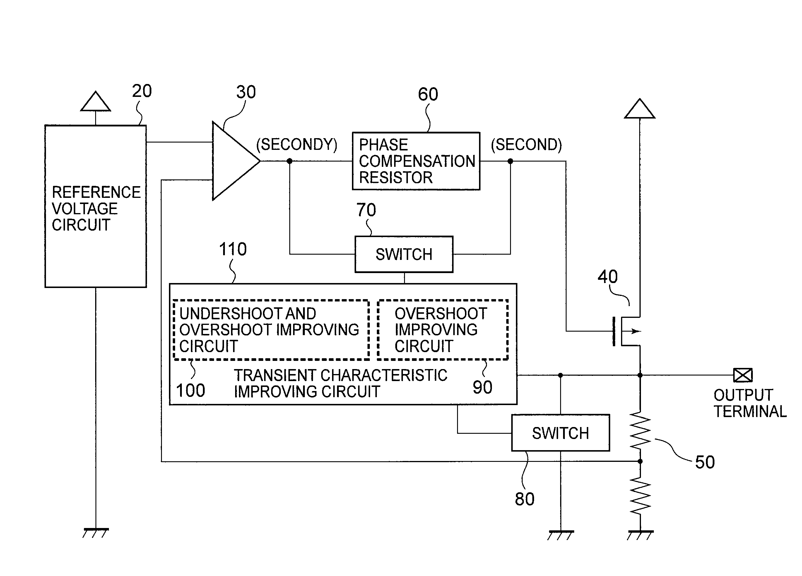
[0048]FIG. 5 illustrates a voltage regulator according to a third embodiment, which has a configuration obtained by combining the first embodiment and the second embodiment. FIG. 6 illustrates a transient characteristic improving circuit 110. The reference voltage circuit 20, the differential amplifier 30, the output transistor 40, the voltage divider circuit 50, the phase compensation resistor 60, and the switch 70 are identical with those in the first embodiment. A difference from the first embodiment resides in that the undershoot and overshoot improving circuit 100 is removed from the voltage regulator, and the transient characteristic improving circuit 110 and a switch 80 are inserted into the voltage regulator.

[0049]The transient characteristic improving circuit 110 is connected to the output terminal of the voltage regulator, and detects an AC component of the output voltage when the output voltage fluctuates, to thereby control the switch 80 to short-circuit the voltage divi...


PUM


Abstract

Provided is a voltage regulator that is capable of improving a transient response characteristic while suppressing current consumption. A fluctuating output voltage is detected without increasing the current consumption of a differential amplifier, and a phase compensation resistor (60) is temporarily short-circuited, to thereby decrease a time constant determined by a parasitic capacitance of an output transistor (40) and the phase compensation resistor (60) to improve the transient response characteristic. Alternatively, a voltage divider circuit (50) is short-circuited to temporarily increase the current consumption and correct the output voltage, with the result that the current consumption during a normal operation is relatively low, and the transient response characteristic is improved by increasing a current only during a transient response.

Description

RELATED APPLICATIONS[0001]This application claims priority under 35 U.S.C. §119 to Japanese Patent Application No. 2009-038146 filed on Feb. 20, 2009, the entire content of which is hereby incorporated by reference.BACKGROUND OF THE INVENTION[0002]1. Field of the Invention[0003]The present invention relates to a voltage regulator that operates so as to keep an output voltage constant.[0004]2. Description of the Related Art[0005]In a technology for a related art voltage regulator, as illustrated in FIG. 9, an output voltage of a reference voltage circuit 21 and a voltage determined by dividing a voltage of an output terminal by a voltage divider resistor 51 are compared with each other by a voltage amplifier circuit 31 to control a PMOS transistor 41. For the purpose of obtaining a stable output voltage with respect to a power fluctuation, there is a need to allow a current to always flow regardless of a power fluctuation level (for example, refer to JP 2001-282371 A). Further, a pha...

Claims


Application Information

Patent Timeline
Patent Type & Authority Patents(United States)
IPC IPC(8): G05F1/00
CPCG05F1/575
Inventor SHITO, RIE
Owner ABLIC INC
Why Eureka
Try Eureka