Differential amplifier circuit that can change current flowing through a constant-current source according to load variation, and series regulator including the same

a technology of constant-current source and amplifier circuit, which is applied in the direction of electric variable regulation, process and machine control, instruments, etc., can solve the problems of unnecessarily increasing the consumption current reducing the transient response characteristic of the differential amplifier circuit, and reducing power efficiency, so as to increase the unnecessary current, increase the circuit scale, and enhance the transient response characteristic

Active Publication Date: 2014-03-04
MITSUMI ELECTRIC CO LTD
View PDF13 Cites 7 Cited by
  • Summary
  • Abstract
  • Description
  • Claims
  • Application Information

AI Technical Summary

Benefits of technology

[0010]An object of the invention is to provide a voltage controlling differential amplifier circuit of a series regulator that can change the current flowing through the constant-current source according to the load variation to enhance the transient response characteristic without increasing the unnecessary current or largely increasing the circuit scale.

Problems solved by technology

However, when a heavy load is connected, the degraded transient response characteristic of the differential amplifier circuit cannot keep the output voltage constant.
However, when the series regulator is used in the light-load system, unfortunately a consumption current of the differential amplifier circuit is unnecessarily increased which causes degradation of power efficiency.
However, the bias current varying circuit disclosed in Japanese Patent Application Laid-Open No. 2004-240646 has a problem in that the power efficiency is decreased.

Method used


Image

  • Differential amplifier circuit that can change current flowing through a constant-current source according to load variation, and series regulator including the same
  • Differential amplifier circuit that can change current flowing through a constant-current source according to load variation, and series regulator including the same
  • Differential amplifier circuit that can change current flowing through a constant-current source according to load variation, and series regulator including the same

Examples


first embodiment

(First Embodiment)

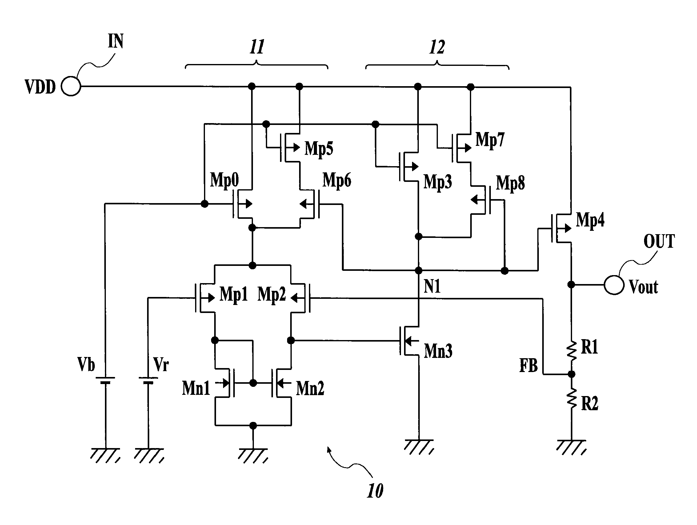
[0019]FIG. 1 is a circuit diagram illustrating a voltage controlling differential amplifier circuit and a series regulator which uses the voltage controlling differential amplifier circuit according to a first embodiment of the present invention.

[0020]A CMOS differential amplifier circuit of the first embodiment includes a differential input stage 11 and an output stage 12. The differential input stage 11 includes a pair of differential MOS transistors (insulated gate field effect transistors) Mp1 and Mp2 whose sources are commonly connected, active load MOS transistors Mn1 and Mn2 (load elements) that are connected to drains of the differential MOS transistors Mp1 and Mp2, respectively, and a constant-current MOS transistor Mp0 (first constant-current source) that is connected between the common source of the differential MOS transistors Mp1 and Mp2 and a power supply voltage VDD. The differential input stage 11 is configured as a CMOS differential amplifier circu...

second embodiment

(Second Embodiment)

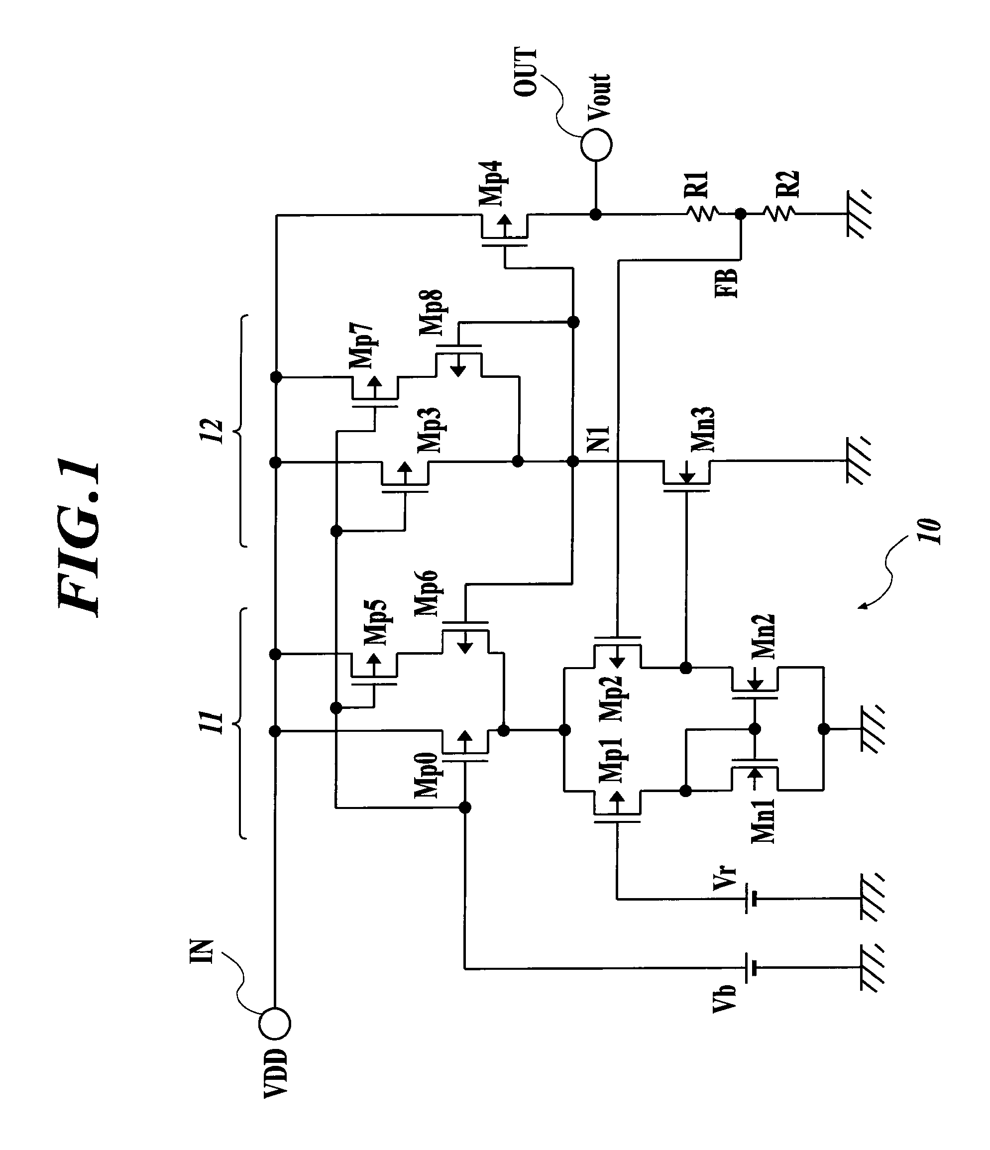
[0026]FIG. 2 is a circuit diagram illustrating the second embodiment of the differential amplifier circuit and the series regulator of FIG. 1.

[0027]In the second embodiment illustrated in FIG. 2, the constant-current source of the output stage 12 in the differential amplifier circuit of the first embodiment is composed of the constant-current MOS transistor Mp3, a first current mirror circuit, and a second current mirror circuit. The first current mirror circuit includes an N-channel MOS transistor Mn4 (first current-voltage conversion MOS transistor) that is connected in series to the constant-current MOS transistor Mp3, and includes a MOS transistor Mn5 (third MOS transistor), wherein the gate of the MOS transistor Mn5 and the gate of the MOS transistor Mn4 are commonly connected. The second current mirror circuit includes a P-channel MOS transistor Mp9 (second current-voltage conversion MOS transistor) that is connected in series to the MOS transistor Mn5, and ...

third embodiment

(Third Embodiment)

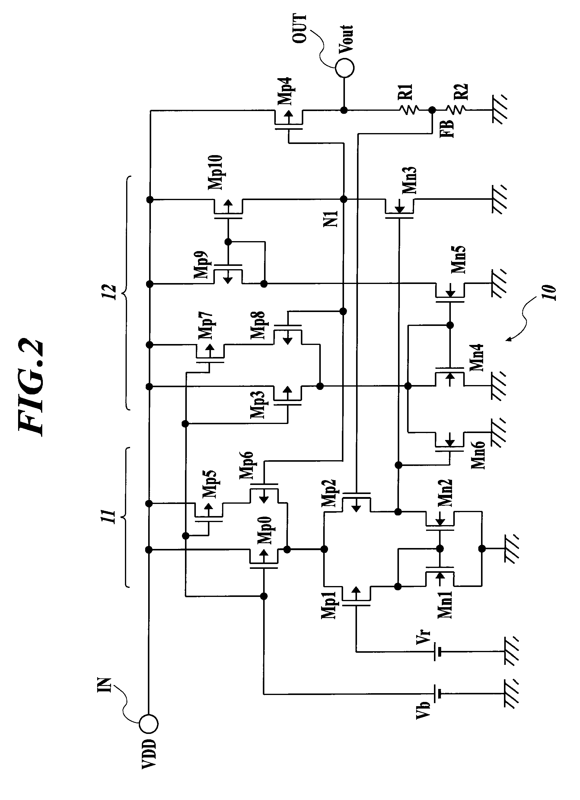
[0032]FIG. 3 is a circuit diagram illustrating the third embodiment of the differential amplifier circuit and the series regulator of FIG. 1.

[0033]The first embodiment illustrated in FIG. 1 is applied to a differential amplifier circuit in which the P-channel MOS transistors are used as the differential MOS transistors Mp1 and Mp2.

[0034]On the other hand, the third embodiment illustrated in FIG. 3 is the example where the present invention is applied to the differential amplifier circuit in which the N-channel MOS transistors are used as differential MOS transistors M1 and M2.

[0035]In the third embodiment, load MOS transistors M3 and M4 composed of P-channel MOS transistors are connected between the drain terminals of the differential MOS transistors M1 and M2 of the differential input stage 11 and the power supply voltage VDD. A constant-current MOS transistor M0 composed of an N-channel MOS transistor is connected between the common source of the differential MOS...


PUM


Abstract

A differential amplifier circuit including: a differential input stage including a pair of differential MOS transistors, a pair of load elements, and a first constant-current source; an output stage including an output MOS transistor and a second constant-current source; a constant-current MOS transistor provided in parallel to one of the first and second constant-current sources; and a boost current controlling MOS transistor in which a potential of a connection node of the output MOS transistor and the second constant-current source is applied to a gate terminal thereof; wherein the boost current controlling MOS transistor is turned on when a voltage inputted to a gate terminal of one of the pair of differential MOS transistors changes, and a current of the constant-current MOS transistor is added to one of the first and second constant-current sources and is allowed to flow.

Description

BACKGROUND OF THE INVENTION[0001]1. Field of the Invention[0002]The present invention relates to a differential amplifier circuit whose transient response characteristic is improved, and particularly to a voltage controlling differential amplifier circuit constituting a direct-current (DC) power supply device such as a series regulator, and a technique which is effectively applied to the series regulator which uses the differential amplifier circuit.[0003]2. Description of Related Art[0004]A series regulator that outputs a constant DC voltage by controlling a resistance value of a control transistor connected between a voltage input terminal and a voltage output terminal is in widespread use as a DC power supply device. In the series regulator, a differential amplifier circuit illustrated in FIG. 4 is used as a circuit that generates a voltage applied to a control terminal (a gate terminal or a base terminal) of the control transistor according to a feedback voltage. A differential ...

Claims


Application Information

Patent Timeline
Patent Type & Authority Patents(United States)
IPC IPC(8): H03F3/45H03F3/30
CPCH03F3/45183H03F2203/45674G05F1/565H03F2203/45528H03F3/347
Inventor SAKURAI, KOHEITERADA, AKIHIROTAKANO, YOICHI
Owner MITSUMI ELECTRIC CO LTD
Why Eureka
Try Eureka