Voltage regulator

a voltage regulator and transient response technology, applied in the field of voltage regulators, can solve the problems of deteriorating voltage regulator transient response characteristics, achieve excellent transient response characteristics, improve the transient response characteristics of voltage regulators, and avoid phase compensation circuit performance sacrifice

Inactive Publication Date: 2011-06-07
ABLIC INC
View PDF4 Cites 5 Cited by
  • Summary
  • Abstract
  • Description
  • Claims
  • Application Information

AI Technical Summary

Benefits of technology

[0011]The present invention has been made in view of the above-mentioned problem, and therefore an object of the present invention is to provide a voltage regulator that is excellent in transient response characteristics even if a resistance of a phase compensation resistor is large.
[0012]In order to solve the above-mentioned problem, in the voltage regulator according to the present invention, a resistor of a phase compensation circuit is so configured as to change the resistance thereof according to a voltage across both ends of the resistor. In a transient state in which an output voltage of an error amplifier circuit changes, the resistance of the resistor in the phase compensation circuit is decreased, to thereby improve the transient response characteristics of the voltage regulator without sacrificing a performance of the phase compensation circuit.
[0013]In the voltage regulator according to the present invention, in the transient state in which the output voltage of the error amplifier circuit changes, the resistance of the resistor in the phase compensation circuit is decreased, to thereby improve the transient response characteristics of the phase compensation circuit. Accordingly, the resistance of the resistor in the phase compensation circuit can be set to be large, and the transient response characteristics of the voltage regulator are excellent.

Problems solved by technology

That is, there arises such a problem that transient response characteristics of the phase compensation circuit 20 are deteriorated, and therefore the transient response characteristics of the voltage regulator are deteriorated.

Method used


Image

  • Voltage regulator
  • Voltage regulator
  • Voltage regulator

Examples


Embodiment Construction

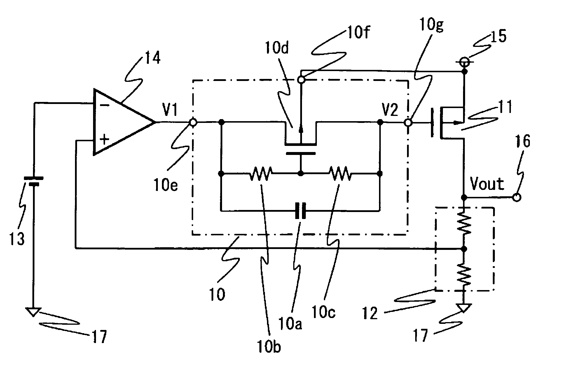
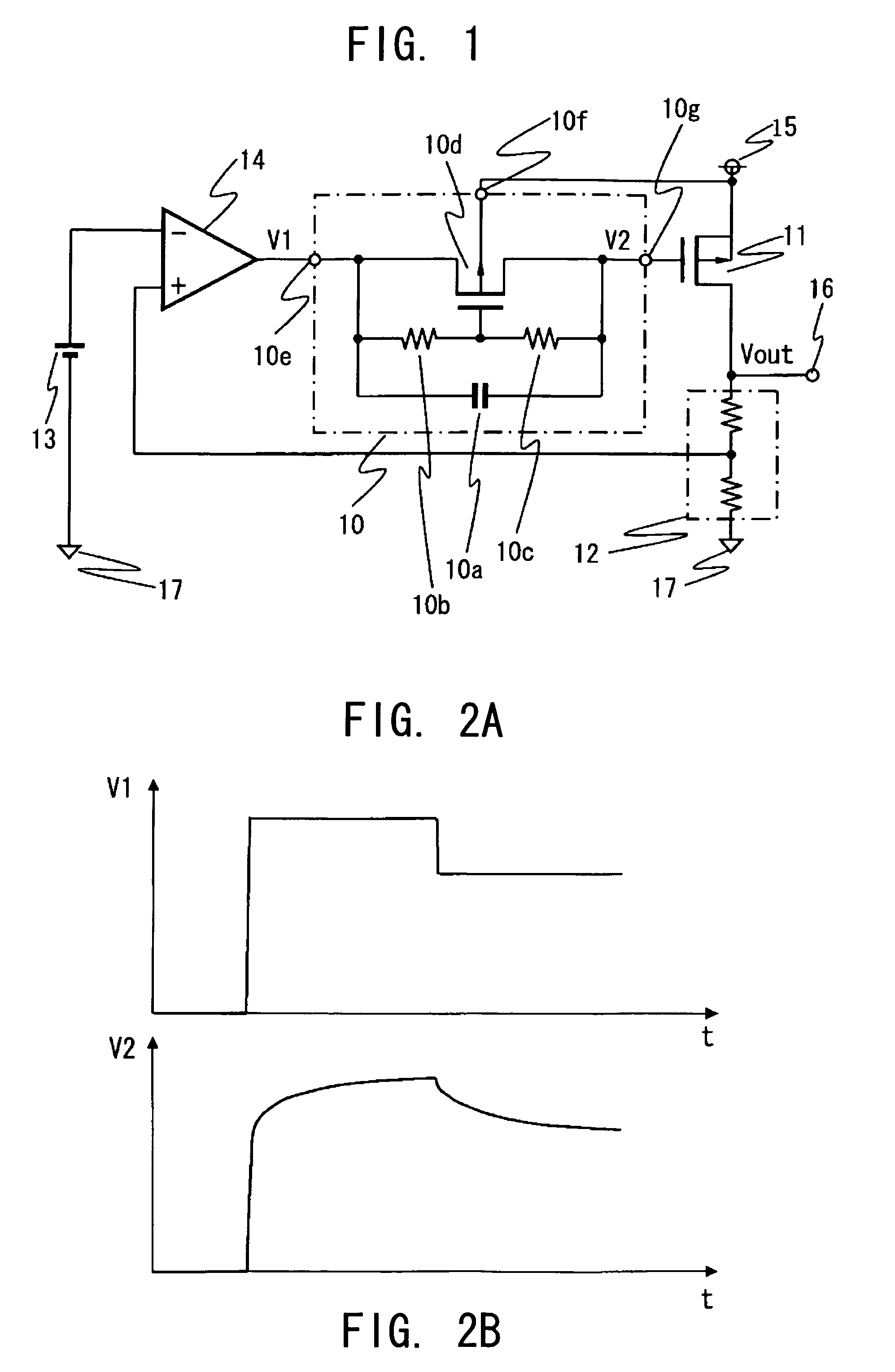
[0019]FIG. 1 is a circuit diagram illustrating a voltage regulator according to the present invention.

[0020]The voltage regulator according to the present invention includes a phase compensation circuit 10, an output transistor 11, a voltage divider circuit 12, a reference voltage circuit 13, an error amplifier circuit 14, a power supply terminal 15, an output terminal 16, and a ground terminal 17. The phase compensation circuit 10 includes a phase compensation capacitor 10a, phase compensation resistors 10b and 10c, a control transistor 10d, an input terminal 10e, an input terminal 10f, and an output terminal 10g.

[0021]The phase compensation circuit 10 has the input terminal 10e connected to an output terminal of the error amplifier circuit 14, the input terminal 10f connected to the power supply terminal 15, and the output terminal 10g connected to a gate of the output transistor 11. The output transistor 11 has a source and a back gate connected to the power supply terminal 15, ...


PUM


Abstract

A voltage regulator has an error amplifier circuit, and a phase compensation circuit having a capacitor connected in parallel to first and second series-connected resistors. A control transistor has its source-drain path connected between input and output terminals of the phase compensation circuit and its gate connected to a junction point between the first and second resistors. In a transient stage in which the output voltage of the error amplifier circuit changes, the resistance of the phase compensation circuit decreases thereby improving the transient response characteristics of the voltage regulator.

Description

BACKGROUND OF THE INVENTION[0001]1. Field of the Invention[0002]The present invention relates to a voltage regulator that outputs a constant output voltage, and more particularly, to a phase compensation circuit that stabilizes an operation of a voltage regulator.[0003]2. Description of the Related Art[0004]FIG. 3 is a circuit diagram illustrating a conventional voltage regulator.[0005]The conventional voltage regulator includes an output transistor 21 that outputs an output voltage Vout, a voltage divider circuit 22 that divides the output voltage Vout, and a reference voltage circuit 23 that generates a reference voltage. The conventional voltage regulator also includes an error amplifier circuit 24 that controls the output transistor 21 so as to hold the output voltage Vout constant on the basis of the output voltage of the voltage divider circuit 22 and the reference voltage, and a phase compensation circuit 20 that is disposed between the output transistor 21 and the error ampl...

Claims


Application Information

Patent Timeline
Patent Type & Authority Patents(United States)
IPC IPC(8): G05F1/44G05F1/56
CPCG05F1/56
Inventor IMURA, TAKASHI
Owner ABLIC INC
Why Eureka
Try Eureka