
Context and Epsilon Stereo Constrained Correspondence Matching

a correspondence matching and context-based technology, applied in the field of matching pixel points in multiple images, can solve the problems of limited availability of matching tools for non-pinhole cameras, and typically provide a larger field of vision than

Inactive Publication Date: 2013-01-03
SEIKO EPSON CORP
View PDF0 Cites 176 Cited by
  • Summary
  • Abstract
  • Description
  • Claims
  • Application Information

AI Technical Summary

Benefits of technology

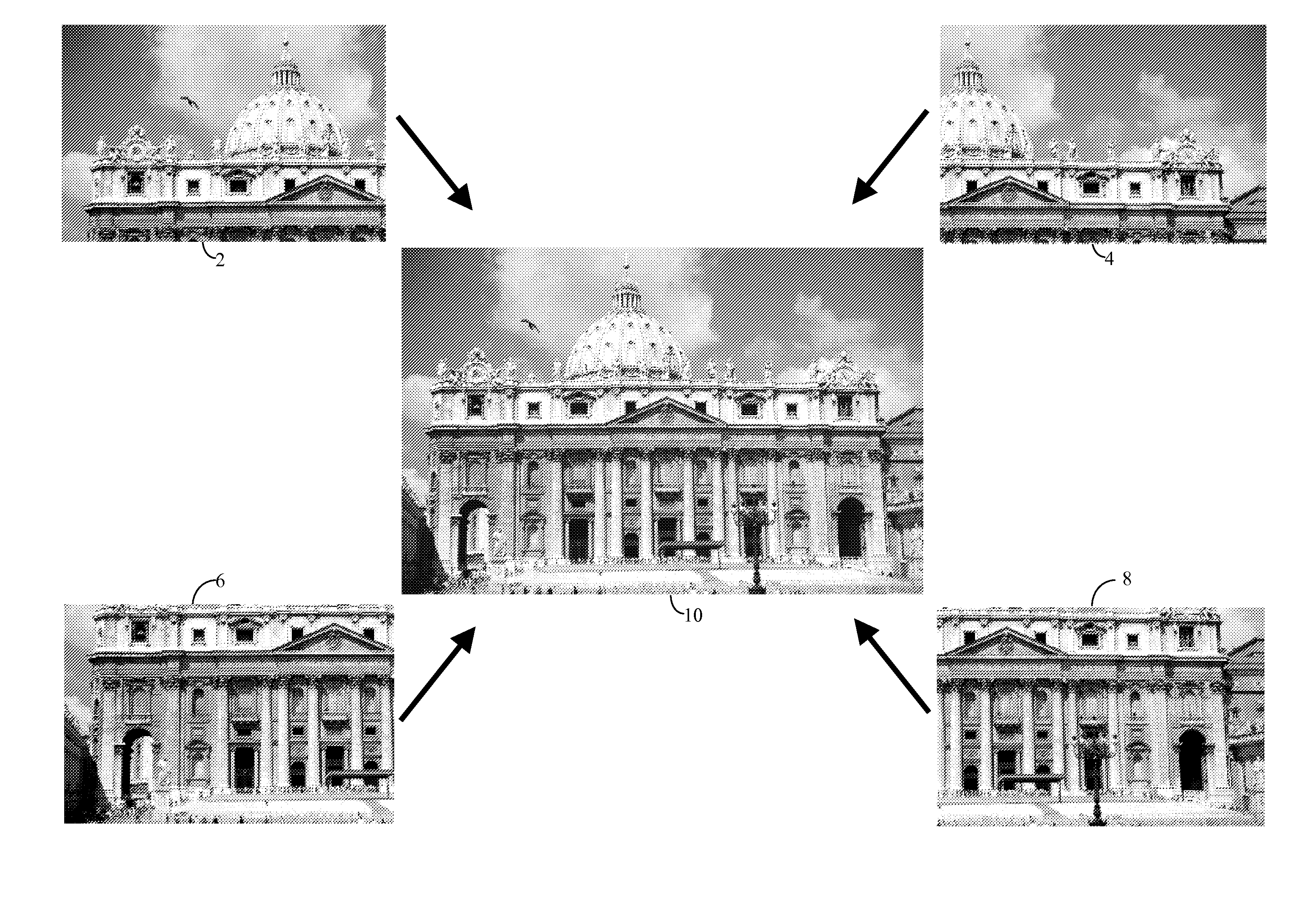
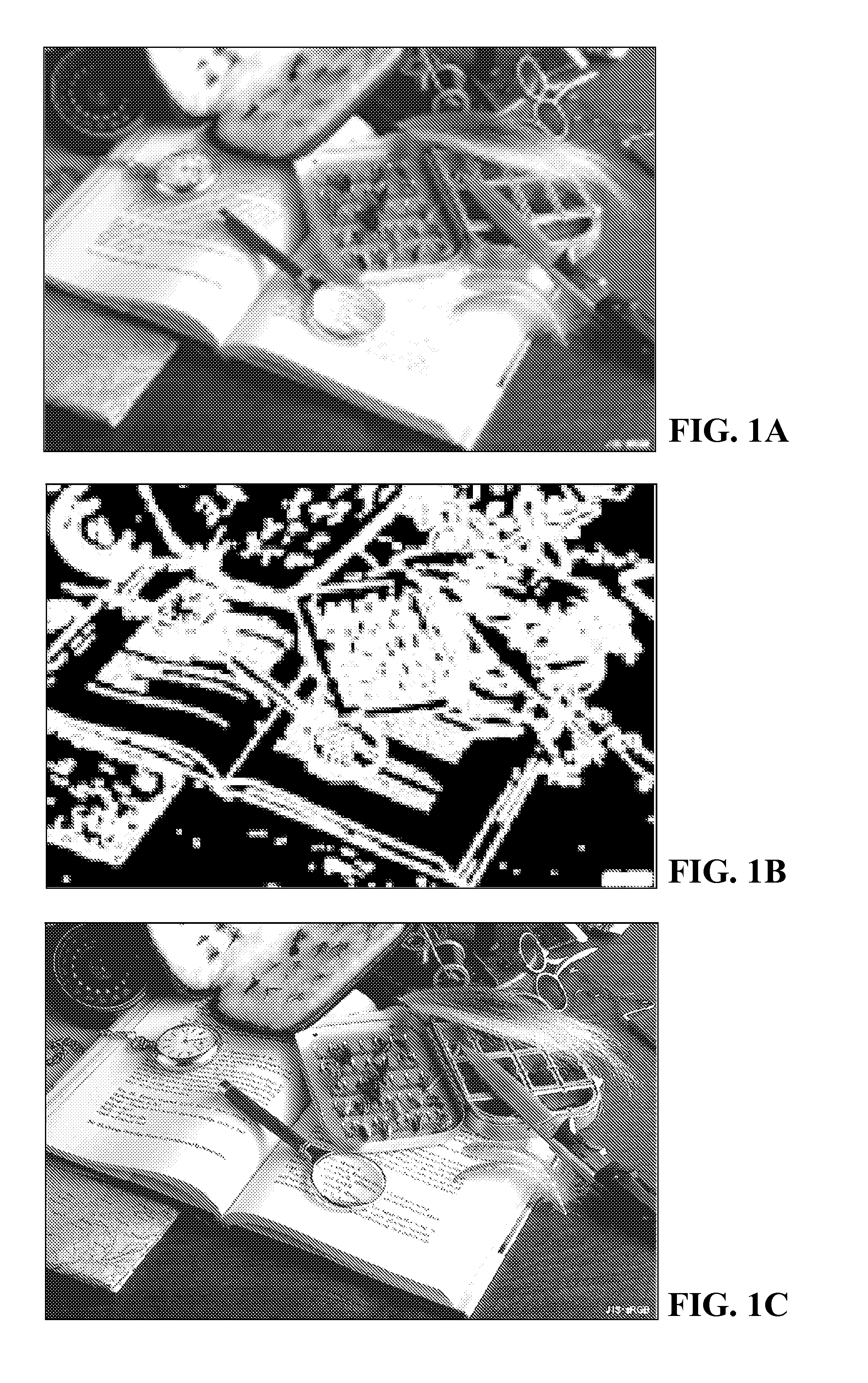
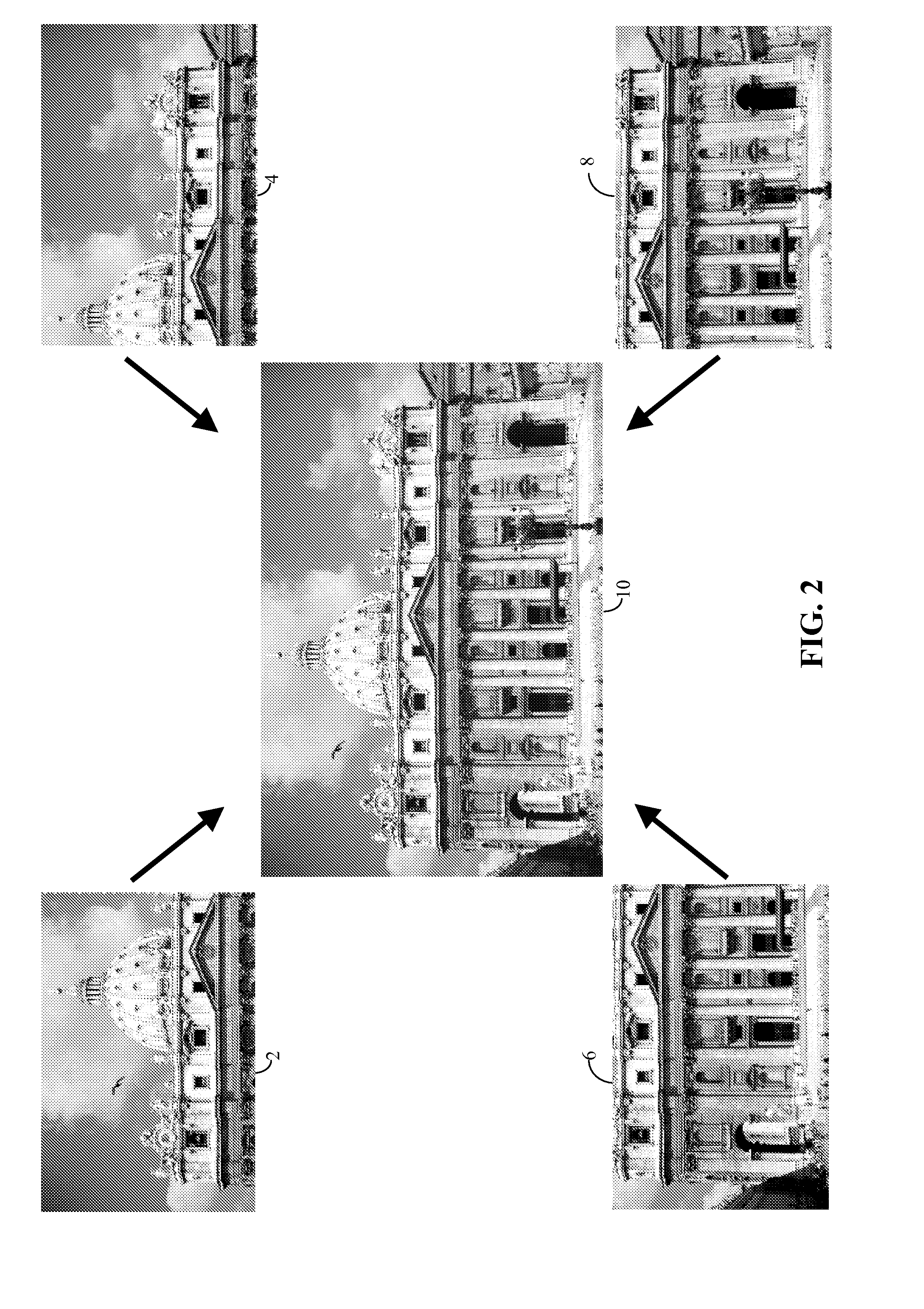
The present invention provides a method for matching pixels in a 3D scene with corresponding pixels in another 3D scene. The method involves identifying target pixels in the first image and potential corresponding pixels in the second image, and calculating the vertical parallax and minimum distance between the target pixels and the potential corresponding pixels. The method also includes applying an affine scale-invariant feature transform (ASIFT) to the first and second images to render a collection of feature point pairs, and identifying edge pixels in the first and second images. The method can be used for matching edge pixels in a 3D scene with corresponding edge pixels in another 3D scene.

Problems solved by technology

Correspondence matching is an essential problem in computer vision, especially in stereo vision, view synthesis, and 3D reconstruction.
As is explained above, however, epipolar geometry and the stereo constraint are based on the pinhole camera model, and thus do not apply to cameras that do not adhere to the pinhole camera model.
Consequently, the availability of corresponding matching tools for non-pinhole cameras has been limited.
Such cameras, however, typically provide a larger field of vision than is possible with pinhole cameras.

Method used


Image

  • Context and Epsilon Stereo Constrained Correspondence Matching
  • Context and Epsilon Stereo Constrained Correspondence Matching
  • Context and Epsilon Stereo Constrained Correspondence Matching

Examples


Embodiment Construction

[0061]Correspondence matching is an essential problem in computer vision, especially in stereo, view synthesis, and 3D reconstruction. Such applications make use of epipolar geometry and are subject to the stereo constraint, which generally applies only camera setups that adhere to the pinhole camera model.

[0062]Catadioptric cameras do not adhere to the pinhole camera model. Consequently, a strict stereo constraint may not exist for such cameras. In general, catadioptric optical systems combine refraction and reflection in an optical system by means of lenses (dioptrics) and curved mirrors (catoptrics). Multi-perspective catadioptric cameras, and camera setups, have an advantage of a wider field of vision, FOV, than is achievable with pinhole camera model setups.

[0063]A simplified example of a catadioptric camera setup 61 is shown in FIG. 5. A perspective camera 65 (or a single-perspective camera, such as a pinhole camera, for creating 2D perspective projection images of 3D scenes) ...


PUM


Abstract

A catadioptric camera having a perspective camera and multiple curved mirrors, images the multiple curved mirrors and uses the epsilon constraint to establish a vertical parallax between points in one mirror and their corresponding reflection in another. An ASIFT transform is applied to all the mirror images to establish a collection of corresponding feature points, and edge detection is applied on mirror images to identify edge pixels. A first edge pixel in a first imaged mirror is selected, its 25 nearest feature points are identified, and a rigid transform is applied to them. The rigid transform is fitted to 25 corresponding feature points in a second imaged mirror. The closes edge pixel to the expected location as determined by the fitted rigid transform is identified, and its distance to the vertical parallax is determined. If the distance is not greater than predefined maximum, then it is deemed correlate to the edge pixel in the first imaged mirror.

Description

BACKGROUND[0001]1. Field of Invention[0002]The present invention generally relates to matching pixel points in multiple images having different view angles, and more specifically relates to edge pixel matching in multiple images taken with catadioptric cameras.[0003]2. Description of Related Art[0004]Edge detection algorithms are part of many image manipulation operations. Edge detection is fundamental to image processing and computer vision, particularly in the areas of feature detection and feature extraction. Edge detection aims to identify points, i.e. pixels that outline objects within an image. There are many edge detection algorithms, but generally they attempt to identify pixels at which discontinuities occurs, i.e. where the image brightness changes sharply. In the ideal case, the result of applying an edge detector to an image leads to a set of connected curves that indicate the boundaries of objects, the boundaries of surface markings, and discontinuities in surface orien...

Claims


Application Information

Patent Timeline
Patent Type & Authority Applications(United States)
IPC IPC(8): H04N5/225H04N13/02G06K9/00H04N13/239
CPCG02B17/0836G02B17/08G06K9/4671G03B37/06H04N13/0239H04N2013/0081G03B37/04G06T15/205H04N13/239G06V10/462
Inventor DING, YUANYUANXIAO, JING
Owner SEIKO EPSON CORP
Learn More