Method and apparatus in a pneumatic material conveying system, and a waste conveying system

a conveying system and waste technology, applied in the field of pneumatic material conveying systems, to achieve the effect of efficient distribution, reliable operation, and effective dimensioning and cost of the drive device of the conveying devi

Inactive Publication Date: 2013-01-03
MARICAP OY
View PDF60 Cites 2 Cited by
  • Summary
  • Abstract
  • Description
  • Claims
  • Application Information

AI Technical Summary

Benefits of technology

[0013]The solution according to the invention has a number of important advantages. When using a solution according to the invention the costs of the early stage of a waste system in extensive construction projects can be distributed better over a longer time span than before. The system can be expanded modularly by means of subsystems. In the solution partial-vacuum generators are arranged in connection with each subsystem such that they can be used to produce the suction, or the suction and blowing, of the system needed in the use of a more extensive system. In this case wastes can be conveyed from the separating means or the accumulator tank of the waste of subsystems in the desired transfer manner to further treatment. The system according to the invention enables reliable operation and in addition it provides an easy possibility for using a backup system, i.e. the partial-vacuum generator of some other subsystem, in a malfunction situation of the partial-vacuum generating apparatus of one subsystem. In addition, the diameter of the conveying piping of a subsystem can be smaller than the diameter of the trunk piping. In this case the power requirement of the partial-vacuum generating apparatus of a subsystem can be kept small and the dimensioning and the costs of the drive devices of the apparatus effective. In this case when conveying wastes from the separating means of a subsystem to the waste station of an extensive system along a trunk pipe, the diameter of which is typically greater than the pipe of the subsystem, the partial-vacuum generating apparatus of a number of subsystems is used to achieve the suction / blowing needed in transfer. In this case the operating power needed for the partial-vacuum generating / blowing of an extensive system can be efficiently distributed into subsystems. In this case an own partial-vacuum generating apparatus is not needed at the waste station.
[0014]In the construction phase of a more extensive system the emptying of subsystems can be performed by using the suction / pressure of the subsystem by transferring wastes e.g. to a tank of a transport means. In this case the transport means can be any transport means whatsoever that comprises a suitable tank, such as a container, or corresponding. By arranging the piping of the system to comprise a circuit where at least a part of the conveying air circulates, the volume of outlet air can be decreased. At the same time the energy consumption of the system decreases. By maintaining a partial vacuum and at the same time maintaining blowing, an effective circulation of conveying air in the circuit and conveying transfer of material in the conveying pipe can be achieved. With the solution according to the invention, it is possible to essentially reduce the volume of outlet air and, at the same time, to reduce possible dust problems and fine particle problems in the outlet pipe. With the solution according to the invention, the noise problem caused by prior art can also be essentially reduced. When the amount of air to be sucked in decreases, the use of energy also decreases. By opening and closing the input points of the system according to the invention, efficient conveying of material into the conveying pipe and transfer in the conveying pipe is achieved, while at the same time it is possible to keep the noise impact caused by the operation of the system small.
[0015]By arranging the conveying pipe of the material conveying system to be composed of operating areas, i.e. subcircuits, the transfer of material in the conveying piping and the emptying of input points into the conveying pipe can be effectively arranged. By arranging the conveying air circulation in the opposite direction an effective removal of clogging can be achieved. The change of the conveying air circulation into the other direction can be arranged easily in a ring piping. The solution according to the invention is suited for use in both conventional conveying systems comprising one or more conveying pipes and conveying systems comprising ring piping.

Problems solved by technology

In this case in the initial phase of a construction project a situation is encountered wherein it is necessary to make sizable investments in equipment, even though the designed full capacity will not be needed in the system for years yet.

Method used


Image

  • Method and apparatus in a pneumatic material conveying system, and a waste conveying system
  • Method and apparatus in a pneumatic material conveying system, and a waste conveying system
  • Method and apparatus in a pneumatic material conveying system, and a waste conveying system

Examples


Embodiment Construction

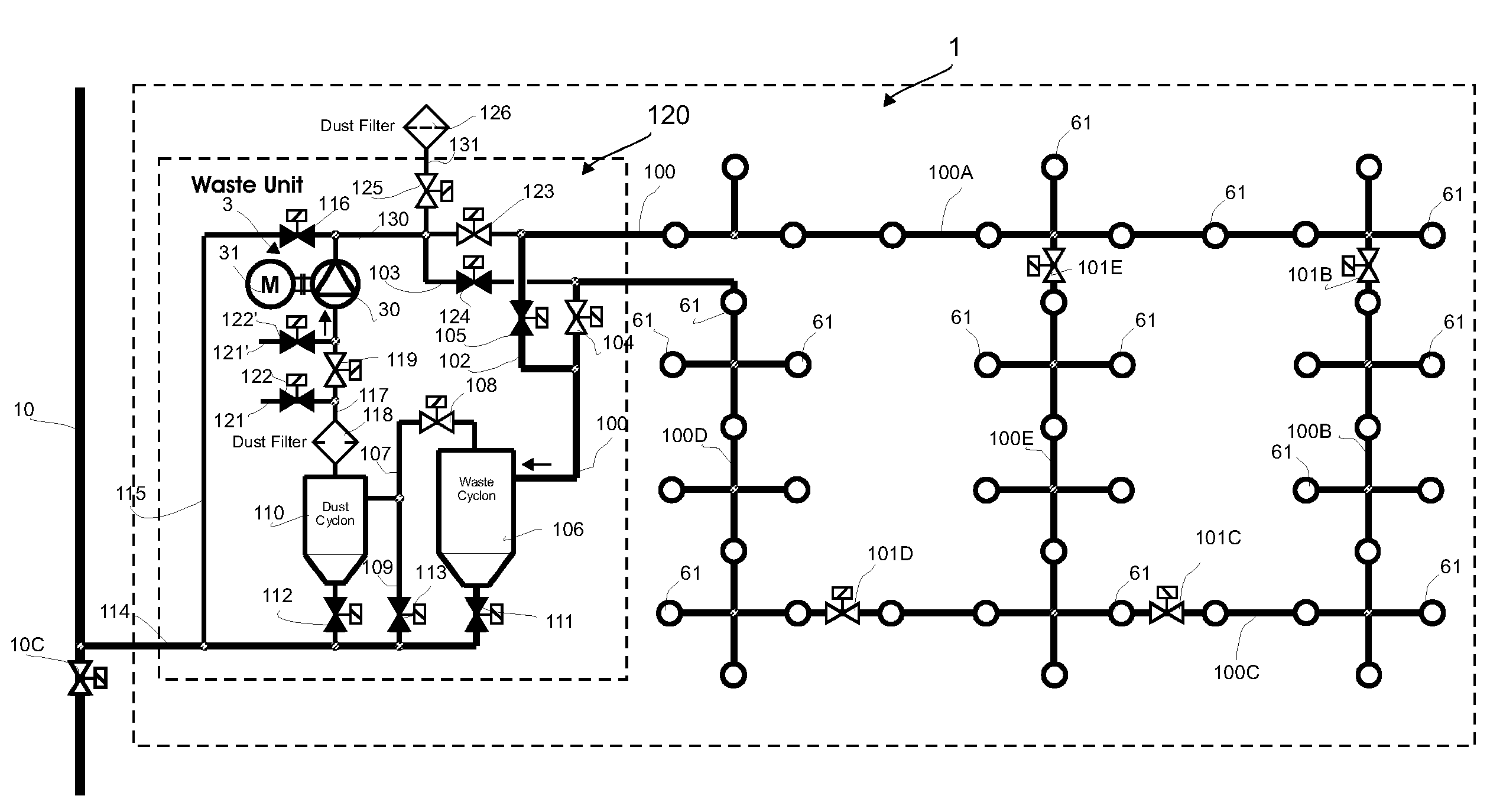
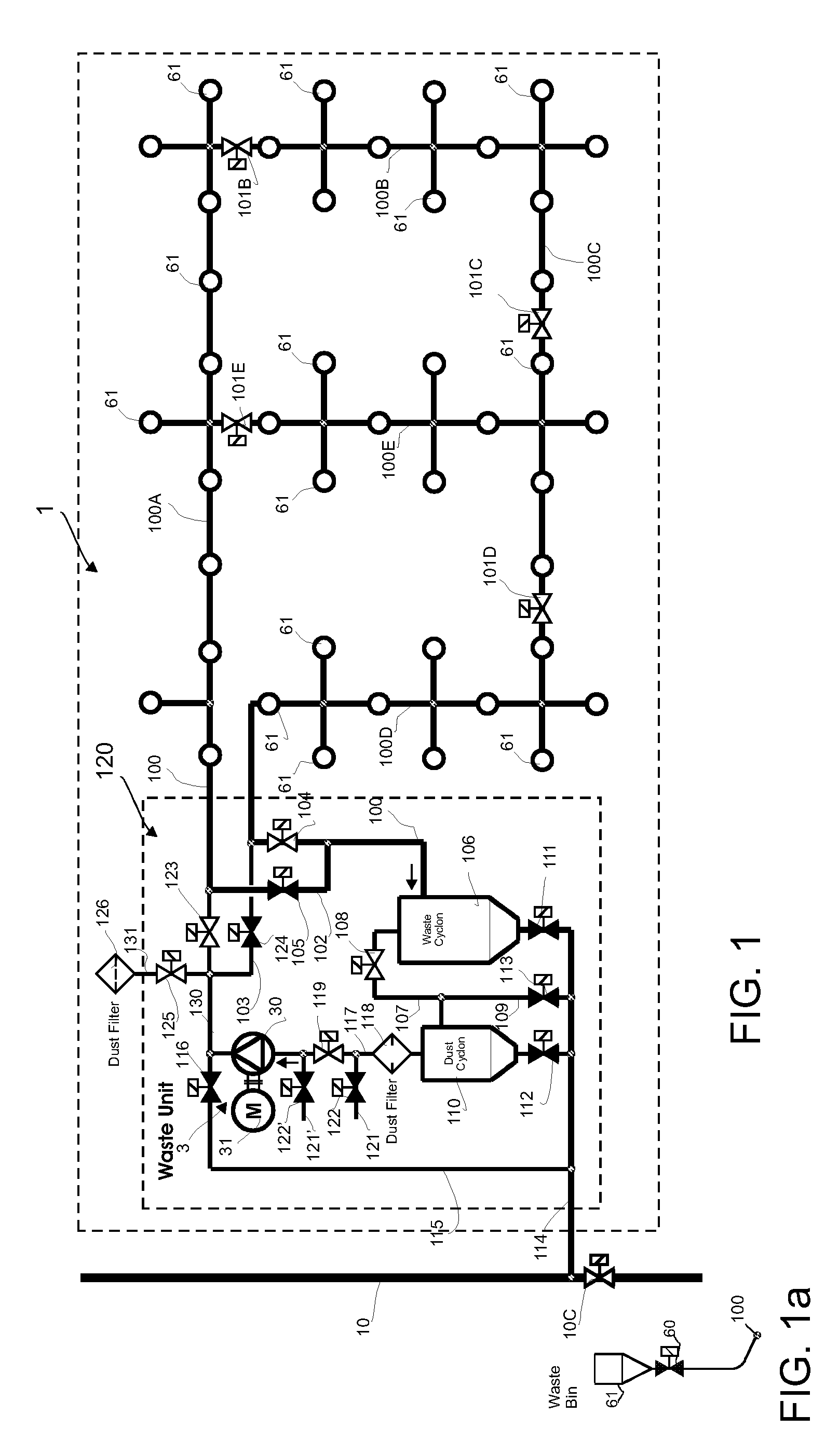
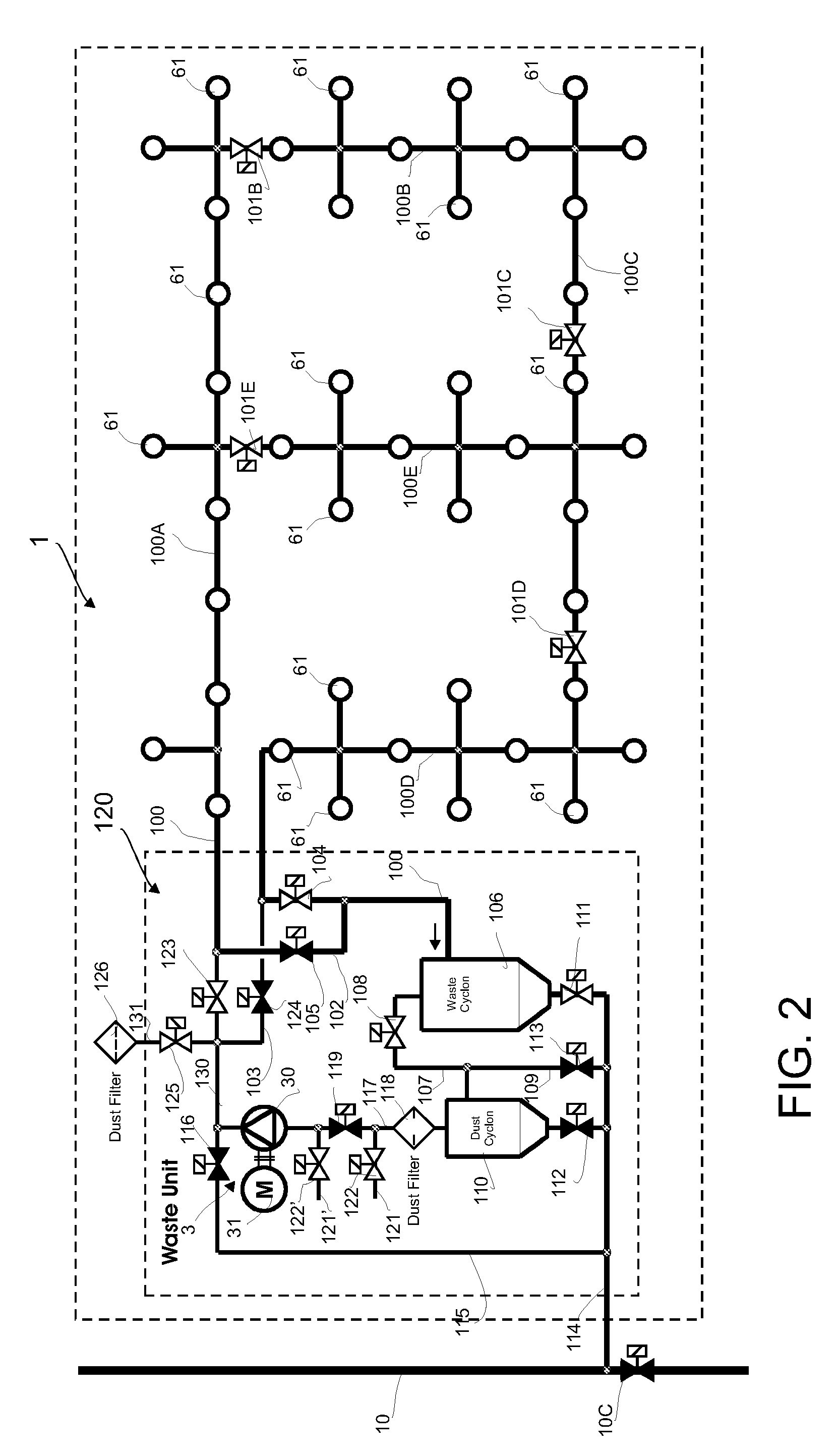
[0031]FIGS. 1-6 present the operation of a subsystem 1 of a material conveying system according to the invention, in different operating phases. FIG. 7 presents the total system, which comprises five subsystems 1 (I, II, III, IV, V) and also a waste station 2 and the necessary conveying piping 10, 11, 12, 114 between the subsystems 1 (I, II, III, IV, V) and the waste station 2.

[0032]FIG. 1 presents a subsystem 1, which comprises a material conveying pipe 100, along the side of which at least one, typically many, input points 61 are arranged. An input point 61 is a feed-in station of material, more particularly of waste material, intended to be conveyed, from which station the material, more particularly waste material, such as household waste, intended to be conveyed is fed into the conveying system. The feed-in station 61 can also be a refuse chute, into which material is fed from input apertures on different floors of a building. The system can comprise a number of feed-in station...


PUM


Abstract

Method in a pneumatic material conveying system, such as in a waste conveying system, which conveying system comprises at least one input point (61) of material, more particularly of waste material, a material conveying pipe (100), which can be connected to an input point (61), and a separating device, in which the material to be transferred is separated from the conveying air, and also means for achieving a pressure difference and / or a conveying air flow in the conveying pipe (100) at least during the transfer of material. In the method material is conveyed from an input point (61) to the separating means (106) or an accumulator tank of a subsystem (1), where the material is separated from the conveying air, and in a second phase the separating means (106) or the accumulator tank of the subsystem (1) is emptied.

Description

BACKGROUND OF THE INVENTION[0001]The object of the invention is a method as defined in the preamble of claim 1.[0002]The object of the invention is also an apparatus as defined in the preamble of claim 10.[0003]The object of the invention is also a pneumatic waste conveying system as defined in the preamble of claim 18.[0004]The invention relates generally to pneumatic material conveying systems, such as to partial-vacuum conveying systems, more particularly to the collection and conveying of wastes, such as to the conveying of household wastes.[0005]Systems wherein wastes are conveyed in piping by means of suction and / or conveying air are known in the art. In these, wastes are conveyed long distances in the piping by sucking. The apparatuses are used for, among other things, the conveying of wastes in different institutions. It is typical to these systems that a partial-vacuum apparatus is used to achieve a pressure difference, in which apparatus a partial vacuum is achieved in the...

Claims


Application Information

Patent Timeline
Patent Type & Authority Applications(United States)
IPC IPC(8): B65F5/00
CPCB65F5/005B65G53/28B65G51/02B65G53/24B65G53/36B65G53/40B65G53/50B65G53/60B65G2201/02B65G2201/04B65G2812/1625B65G2812/1691
Inventor SUNDHOLM, GORAN
Owner MARICAP OY
Why Eureka
Try Eureka