
Wireless communication system, femtocell base station and transmission power control method

a wireless communication and transmission power technology, applied in power management, network topologies, network traffic/resource management, etc., can solve the problems of mutual interference, difficult to secure an exclusive frequency band for the femtocell base station, and mutual interference between downlink wireless lines, so as to reduce the interference of downlink wireless lines, improve connectivity to an adjacent femtocell base station, and minimize the influence

Inactive Publication Date: 2013-01-03
PANASONIC INTELLECTUAL PROPERTY CORP OF AMERICA
View PDF1 Cites 66 Cited by
  • Summary
  • Abstract
  • Description
  • Claims
  • Application Information

AI Technical Summary

Benefits of technology

The wireless communication system and method described in the patent text can reduce interference between adjacent femtocell base stations, improving connectivity for wireless terminals while minimizing the impact on other wireless terminals. This results in better overall performance of the wireless network.

Problems solved by technology

Therefore, it is difficult to secure an exclusive frequency band for the femtocell base station.
When the femtocell base station is introduced into the existing cellular system on the basis of these conditions, there is a problem of mutual interference between downlink wireless lines provided for a wireless terminal (MUE: Macro User Equipment) connected to the existing macrocell base station from the femtocell base station and a wireless terminal (HUE: Home User Equipment) connected to the femtocell base station from the existing macrocell base station.
In addition, there is a problem of mutual interference between downlink wireless lines provided for a femtocell user (for example, a user of the femtocell base station installed on the adjacent house) who has not obtained access authorization from the femtocell base station.

Method used


Image

  • Wireless communication system, femtocell base station and transmission power control method
  • Wireless communication system, femtocell base station and transmission power control method
  • Wireless communication system, femtocell base station and transmission power control method

Examples


first embodiment

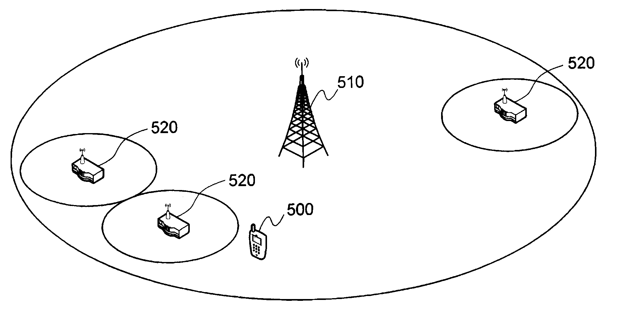
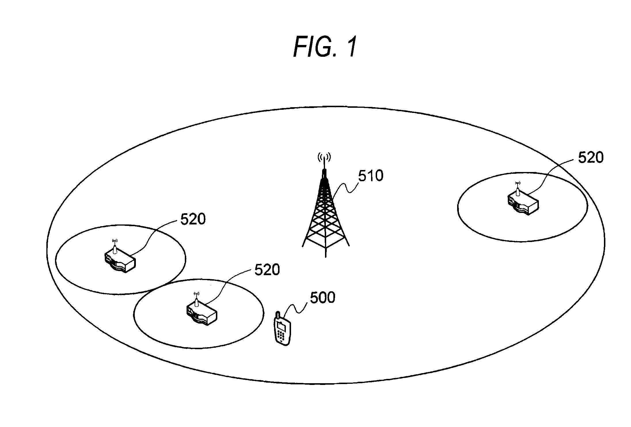
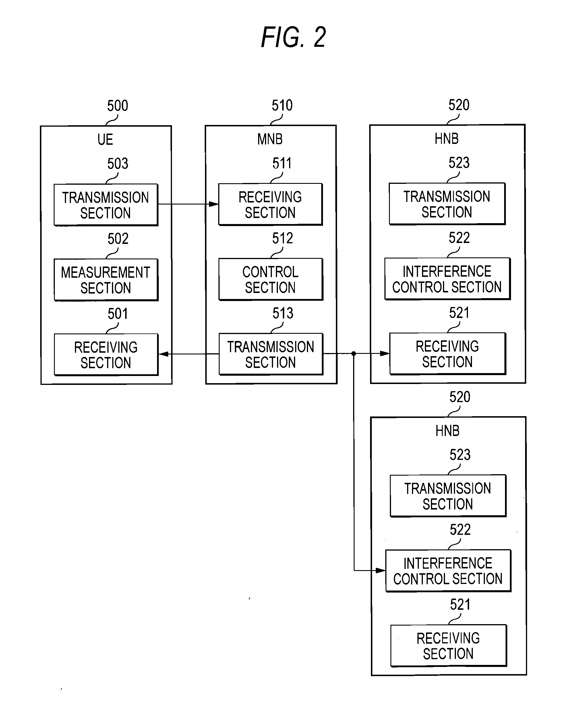
[0059]FIG. 1 is a block diagram illustrating a configuration of a wireless communication system according to a first embodiment of the invention. FIG. 2 is a block diagram illustrating each configuration of a wireless terminal, a macrocell base station and femtocell base stations which are included in the wireless communication system according to the first embodiment.

[0060]The wireless communication system according to the first embodiment shown in FIG. 1 includes a wireless terminal (UE) 500, a macrocell base station (MNB) 510, and a plurality of femtocell base stations (HNB) 520. Meanwhile, the terminal and the base stations are operated by the same communication system (for example, WCDMA, LTE, WLAN and the like).

[0061]As shown in FIG. 2, the wireless terminal (UE) 500 includes a receiving section 501, a measurement section 502, and a transmission section 503. In FIG. 1, the wireless terminal 500 receives an offer of a downlink communication service from the macrocell base stati...

second embodiment

[0098]In the first embodiment, the local station femtocell base station reduces the transmission power of the local station when it is determined to be an adjacent femtocell terminal up to a lower limit. However, when the local station femtocell base station reduces the transmission power of the local station up to a lower limit during the connection to the local station femtocell terminal to thereby narrow the coverage, there may be a case where the connection between the local station femtocell terminal and the local station femtocell base station is cut off.

[0099]In a wireless communication system of a second embodiment, when the local station femtocell base station reduces the transmission power during the connection to the local station femtocell terminal in addition to the downlink transmission power reduction control method described in the first embodiment, the amount of reduction is controlled in accordance with a communication state of the local station femtocell terminal....

third embodiment

[0111]In the first embodiment, when the identifier of the wireless terminal included in the interference control request from the macrocell base station is included in the adjacent UE list of the local station, each reference signal received power value of the adjacent femtocell base station and the local station is included in the interference control request, and the reference signal received power value of the local station is larger than that of the adjacent femtocell base station, the local station femtocell base station determines the wireless terminal to be an adjacent femtocell terminal (HUE). For this reason, when the above-mentioned conditions are satisfied even in the case where the wireless terminal comes close to the adjacent femtocell base station from the location side of the local station femtocell base station and the case where it moves away from the adjacent femtocell base station through the local station femtocell base station side, the local station femtocell b...


PUM


Abstract

A wireless terminal transmits a result of measuring received power of a downlink wireless signal from a femtocell base station to a macrocell base station. The macrocell base station transmits an interference control request including identification information of the wireless terminal to a femtocell base station group of which received power of a downlink signal included in a measurement result transmitted from the wireless terminal is a predetermined value or more. The femtocell base station has an adjacent wireless terminal list in which identification information of a wireless terminal, which is capable of being connected to an adjacent femtocell base station but is not capable of being connected to the femtocell base station, is recorded, and downlink transmission power of the femtocell base station is reduced when the identification information included in the interference control request is included in this list.

Description

TECHNICAL FIELD[0001]The present invention relates to a wireless communication system, a femtocell base station and a transmission power control method which are capable of reducing interference of a downlink wireless line between adjacent femtocell base stations.BACKGROUND ART[0002]It has been considered to introduce an ultra-compact wireless base station (hereinafter, referred to as a “femtocell base station (HNB: Home Node B)”) into a cellular system represented by WCDMA (Wideband Code Division Multiple Access) or LTE (Long Term Evolution). The femtocell base station can cover an area of appropriately several meters in radius (hereinafter, referred to as a “femtocell”). The femtocell base station is installed within, for example, buildings such as ordinary households or offices having relatively bad propagation environment. In this manner, in the cellular system, a speeding up of wireless transmission within the femtocell is anticipated even in an area having bad propagation envi...

Claims


Application Information

Patent Timeline
IPC IPC(8): H04W52/18
CPCH04W24/10H04W52/244H04W52/247H04W92/20H04W28/048H04W52/143H04W88/08H04W84/045H04W28/04
Inventor NAKA, KATSUYOSHIUE, TOYOKIKANAZAWA, TAKESHI
Owner PANASONIC INTELLECTUAL PROPERTY CORP OF AMERICA
Learn More