Method for Manufacturing Nut for Ball Screw and Ball Screw

a manufacturing method and technology for ball screws, applied in gearing, forging/pressing/hammering apparatuses, forging equipment, etc., can solve the problems of insufficient strength, easy damage, and elongated working head of dies

Active Publication Date: 2013-01-10
NSK LTD
View PDF15 Cites 7 Cited by
  • Summary
  • Abstract
  • Description
  • Claims
  • Application Information

AI Technical Summary

Benefits of technology

[0040]According to a method of the present invention, it is possible to form a concave without damaging a die, even in a case where a nut having a long axial dimension and a small diameter is manufactured, as a method of directly forming a ball return passage directly on an inner circumferential surface of a nut blank by plastic working.

Problems solved by technology

It is to be noted, however, that the method described in Patent Document 1 has a problem in that when the axial dimension of the nut is long and the inner diameter is small, the working head of the die is elongated and the strength is insufficient and it is easily damaged.

Method used


Image

  • Method for Manufacturing Nut for Ball Screw and Ball Screw
  • Method for Manufacturing Nut for Ball Screw and Ball Screw
  • Method for Manufacturing Nut for Ball Screw and Ball Screw

Examples


first embodiment

First Example

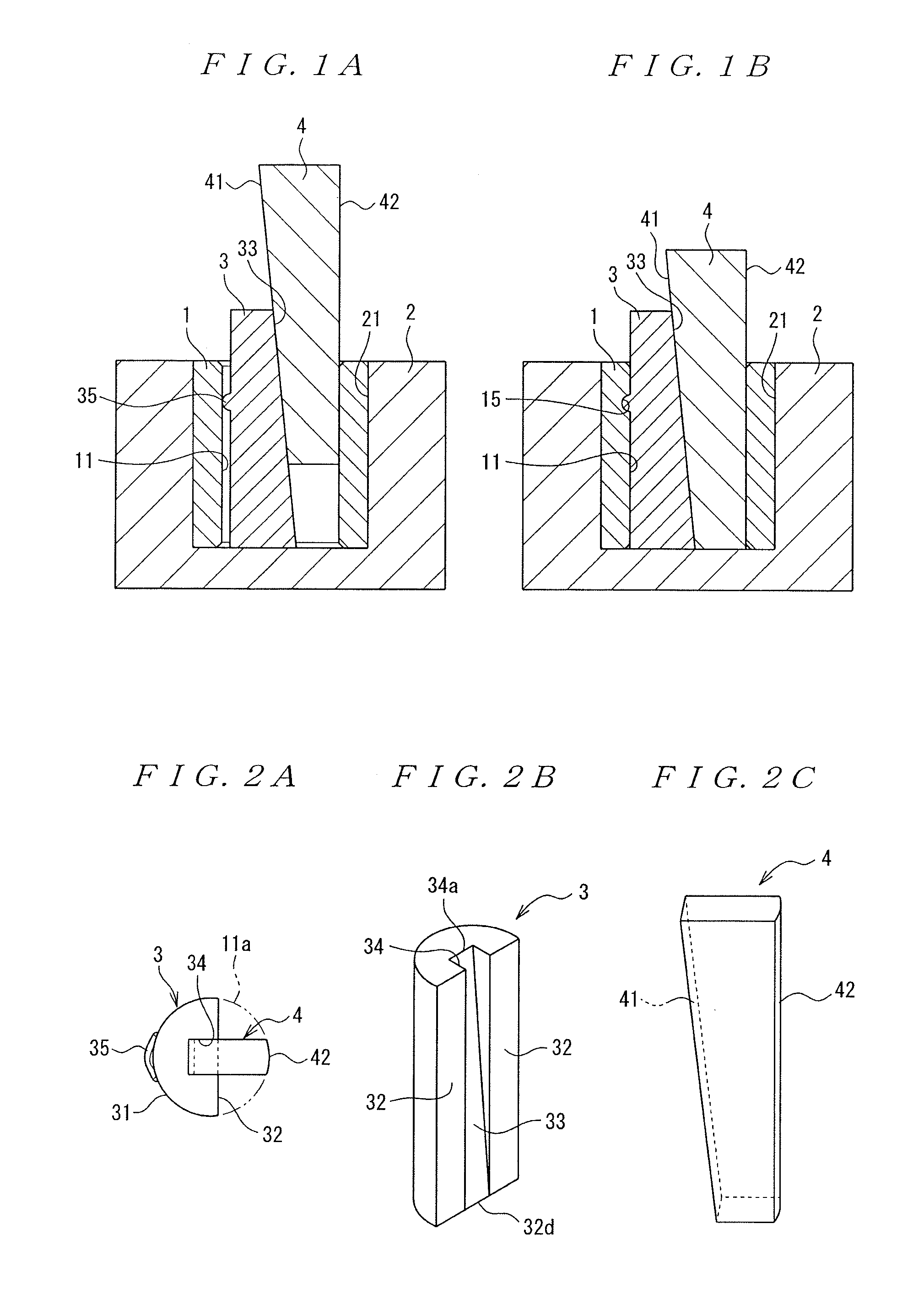
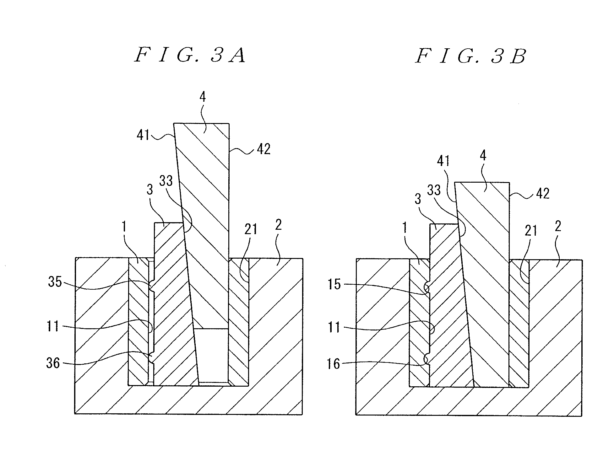
[0140]The die described in a first example is, referring to FIG. 1, provided with: a blank holder 2 having a concave 21 for holding a nut blank 1; and a cam slider 3 and a cam driver 4 disposed at the inside of the nut blank 1.

[0141]Referring now to FIG. 2A and FIG. 2B, the cam slider 3 is a substantially semicircular column shaped member having an outer circumferential surface 31 and a plane 32 parallel to the axial direction. The diameter of a circle constituted with the outer circumferential surface 31 is slightly smaller than that of a circle 11a constituted with an inner circumferential surface 11 of the nut blank 1. There is provided an inclined surface 33, extending in the axial direction at the midpoint of the radial direction, at the plane 32 of the cam slider 3. The inclined surface 33 corresponds to a plane connecting a bottom surface line 34a of a concave 34 at one end (upper end) in the axial direction with a line 32d forming a lower end of the plane 32. Ad...

second embodiment

[0220]A second embodiment relates to a method for manufacturing a nut included in a ball screw.

[0221]The ball screw is provided with: a nut having an inner circumferential surface on which a spiral groove is formed; a threaded shaft having an outer circumferential surface on which a spiral groove is formed; balls loaded in a raceway between the spiral groove of the nut and that of the threaded shaft; and a ball return passage for returning the balls from an end point of the raceway to a start point thereof. The ball screw is a device such that the balls are rolling in the raceway to make the nut relatively move with respect to the threaded shaft.

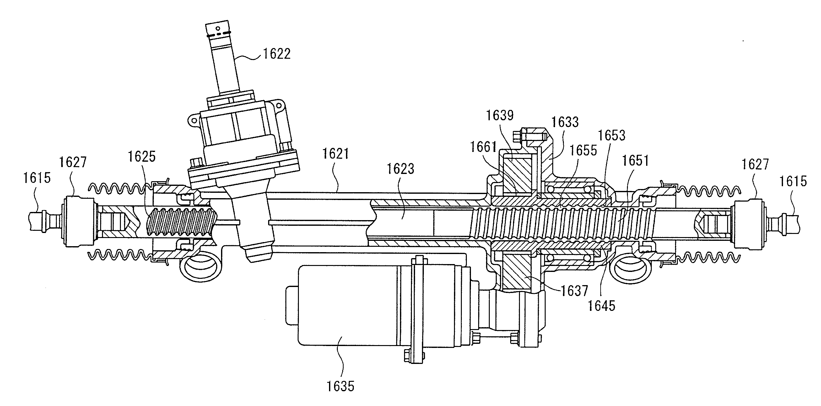
[0222]Such ball screws are used in not only positioning devices of general industrial machinery but also in electrical actuators mounted on vehicles such as automobiles, motorcycles, or vessels.

[0223]As to the ball return passage in the ball screw, there are a circulation tube type of the ball return passage and a deflector type thereof. In ...

third embodiment

[0250]A third embodiment relates to a method for manufacturing a ball screw and a ball screw manufactured by the method.

[0251]A ball screw is provided with: a nut having an inner circumferential surface on which a spiral groove is formed; a threaded shaft having an outer circumferential surface on which a spiral groove is formed; balls loaded in a raceway between the spiral groove of the nut and that of the threaded shaft; and a ball return passage for returning the balls from an end point of the raceway to a start point thereof. The ball screw is a device such that the balls are rolling in the raceway to make the nut relatively move with respect to the threaded shaft.

[0252]Such ball screws are used in not only positioning devices of general industrial machinery but also electrical actuators mounted on vehicles such as automobiles, motorcycles, or vessels.

[0253]As to the ball return passage in the ball screw, there are a circulation tube type of the ball return passage and a deflect...


PUM

PropertyMeasurementUnit
angleaaaaaaaaaa
distanceaaaaaaaaaa
shapeaaaaaaaaaa

Abstract

A method forms a concave constituting a ball return passage directly on an inner circumferential surface of a nut blank by plastic working without damaging a die. Letter S shaped concaves are formed on an inner circumferential surface of a nut blank, by pressing by use of a die having a blank holder, a cam driver, cam sliders, and a cylindrical member. The cam driver has inclined surfaces having the same angle of inclination as the cam sliders. The cam sliders have letter S shaped convexes corresponding to the letter S shaped concaves, and are held by through holes, respectively. When the cam driver is pressed from the top thereof, the cam sliders move outwardly in the radial direction, respectively, and the letter S shaped convexes push the inner circumferential surface of the nut blank for plastic deformation.

Description

TECHNICAL FIELD[0001]The present invention relates to a method for manufacturing a nut constituting a ball screw. The present invention also relates to a ball screw.BACKGROUND ART[0002]A ball screw is provided with: a nut having an inner circumferential surface on which a spiral groove is formed; a threaded shaft having an outer circumferential surface on which a spiral groove is formed; balls loaded in a raceway between the spiral groove of the nut and that of the threaded shaft; and a ball return passage for returning the balls from an end point of the raceway to a start point thereof. The ball screw is a device such that the balls are rolling in the raceway to make the nut relatively move with respect to the threaded shaft.[0003]Such ball screws are used in not only positioning devices of general industrial machinery but also electrical actuators mounted on vehicles such as automobiles, motorcycles, or vessels.[0004]As to the ball return passage in the ball screw, there are a cir...

Claims


Application Information

Patent Timeline
Patent Type & Authority Applications(United States)
IPC IPC(8): B21K1/70F16H25/22
CPCB21J5/12B21K1/04B21K1/70B21K21/12B21K21/16Y10T74/19767B21J13/025F16H2025/2481F16H25/2223Y10T74/19749B21K23/00Y10T74/19772B21J5/02F16H25/22F16H25/24
Inventor WATANABE, ATSUSHIHARADA, TORUYOKOYAMA, SHOUJIOOTSUKA, KIYOSHIHASHIMOTO, KOJIKOBAYASHI, KAZUTONAKAMURA, TOSHIOMOGI, SHINOBUSAITOU, SHINGOYAMASHITA, TOMOFUMI
Owner NSK LTD
Why Eureka
Try Eureka