Charger and charging apparatus

a charging apparatus and charging circuit technology, applied in the direction of electric vehicles, electric devices, transportation and packaging, etc., can solve the problems of inability to meet the requirements of charging time, so as to reduce the breakdown voltage and mechanical deterioration of the electrode plate of the battery, the effect of reducing the charging time and reducing the breakdown voltag

Active Publication Date: 2013-01-10
TAKAHASHI SACHIO +1
View PDF6 Cites 19 Cited by
  • Summary
  • Abstract
  • Description
  • Claims
  • Application Information

AI Technical Summary

Benefits of technology

[0017]According to the charger and the charging apparatus of the present invention, since the first voltage having a predetermined voltage value and the second voltage having a predetermined voltage value different from this first voltage are alternately supplied, abrupt supply from 0 V is no longer performed, reduction in breakdown voltage and mechanical deterioration of an electrode plate of the battery can be suppressed.
[0018]Additionally, since the plurality of chargers are provided and the plurality of batteries are connected to the respective charger based on a one-to-one correspondence, the charging voltage can be reduced, and a large amount of charging current is allowed to flow. As a result, the charging time can be greatly reduced.

Problems solved by technology

However, when the assembled battery is charged in such a configuration, a considerable time is required until completion.
For example, as shown in FIG. 10, when a substantially fixed amount of charging voltage is continuously supplied, a long charging time of approximately eight hours is required.
In this case, a user has to wait for eight hours until the next driving, which is not practical.

Method used


Image

  • Charger and charging apparatus
  • Charger and charging apparatus
  • Charger and charging apparatus

Examples


Embodiment Construction

[0029]A preferred embodiment of a charger and a charging apparatus according to the present invention will now be described hereinafter with reference to drawings.

[Configurations of Charger and Charging Apparatus]

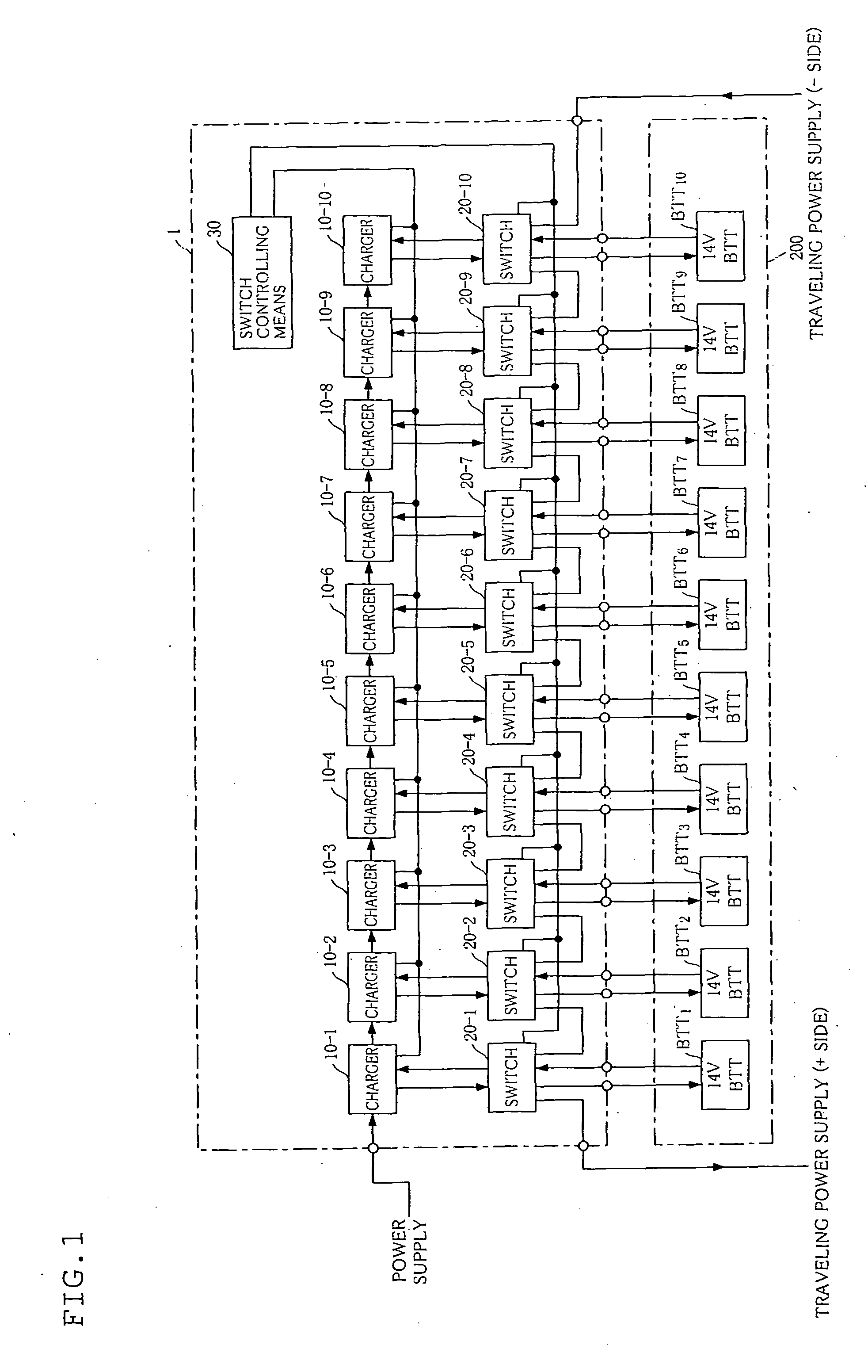
[0030]Configurations of a charger and a charging apparatus according to the present invention will be first described with reference to FIG. 1.

[0031]This drawing is a block diagram showing a configuration of a charging apparatus according to this embodiment.

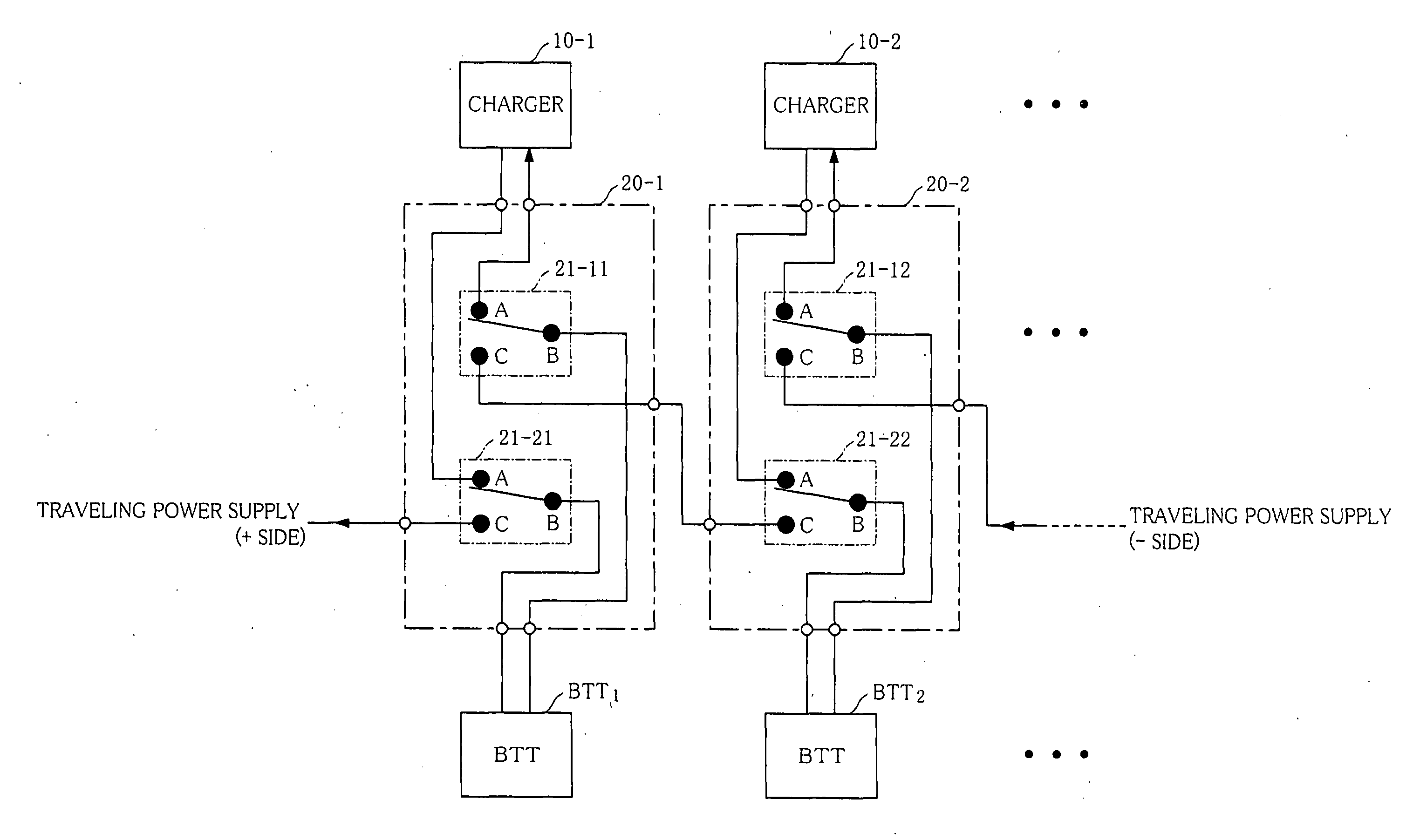
[0032]As shown in the drawing, a charging apparatus 1 comprises a plurality of chargers 10 (10-1 to 10-10), switches 20 (20-1 to 20-10), and switch controlling means 30.

[0033]Here, the plurality of chargers 10 are provided. In particular, the same number / higher number of the chargers 10 as / than charging target batteries can be provided. For example, when an assembled battery 200 having a plurality of (10 in the drawing) coupled storage batteries BTT therein is a charging target, the same number (10 in the drawing) / higher...


PUM


Abstract

A reduction in breakdown voltage and mechanical deterioration of an electrode plate of a rechargeable battery are suppressed, and a charging time is shortened.
There is provided a charger 10 which charges a rechargeable battery, comprising: a first output unit which outputs a first voltage; a second output unit which outputs a second voltage having a predetermined voltage value different from that of the first voltage; a charge control unit 16 which inputs the first voltage and the second voltage, alternately outputs these voltages, and supplies them to the rechargeable battery as charging voltages; a charged-amount detection unit 14 which measures a charged amount of the rechargeable battery; and an output control unit 15 which carries out control in such a manner that an output time of the first voltage and/or the second voltage in the charge control unit 15 is prolonged as the charged amount increases.

Description

TECHNICAL FIELD [0001]The present invention relates to a charger that charges a rechargeable battery (a battery) mounted in a vehicle and a charging apparatus comprising the plurality of chargers, and more particularly to a charger and a charging apparatus which realize quick charging.BACKGROUND ART [0002]In each of vehicles such as an electric-powered car and a hybrid car, a power battery or an auxiliary battery is mounted. As this kind of battery, there is often used a so-called assembled battery in which many storage batteries are connected in series.[0003]Further; each of some vehicles has a charger which is used for charging a battery mounted therein. The charger converts a commercial power source of 100 V or 200 V into a predetermined voltage and supplies the converted voltage to a battery, whereby the battery is charged.[0004]When this charger is used to charge the assembled battery, as shown in FIG. 9, a predetermined voltage is applied to the entire assembled battery 200 to...

Claims


Application Information

Patent Timeline
Patent Type & Authority Applications(United States)
IPC IPC(8): H02J7/00
CPCH02J7/0091B60L3/0046H02J7/0093H02J7/00711H02J7/007194
Inventor TAKAHASHI, SACHIOFUDA, KAZUO
Owner TAKAHASHI SACHIO
Why Eureka
Try Eureka