
Lighting apparatus, backlight module and display apparatus

a backlight module and light source technology, applied in lighting and heating apparatus, planar/plate-like light guides, instruments, etc., can solve the problems of unfavorable lightness and slimness of products, the thickness of light-guiding plates needs to be increased, etc., to achieve the effect of enhancing lighting brightness, increasing the number of light sources, and reducing brightness

Active Publication Date: 2013-01-10
INNOLUX CORP +1
View PDF0 Cites 4 Cited by
  • Summary
  • Abstract
  • Description
  • Claims
  • Application Information

AI Technical Summary

Benefits of technology

The present invention is a lighting apparatus, backlight module, and display apparatus that are designed to be slimmer while still maintaining brightness. The invention uses side view lighting units that are placed at different distances from a reference line, which allows for more light sources to be used without increasing the thickness of the light-guiding plate. This results in a slimmer product and increased competitiveness in the market.

Problems solved by technology

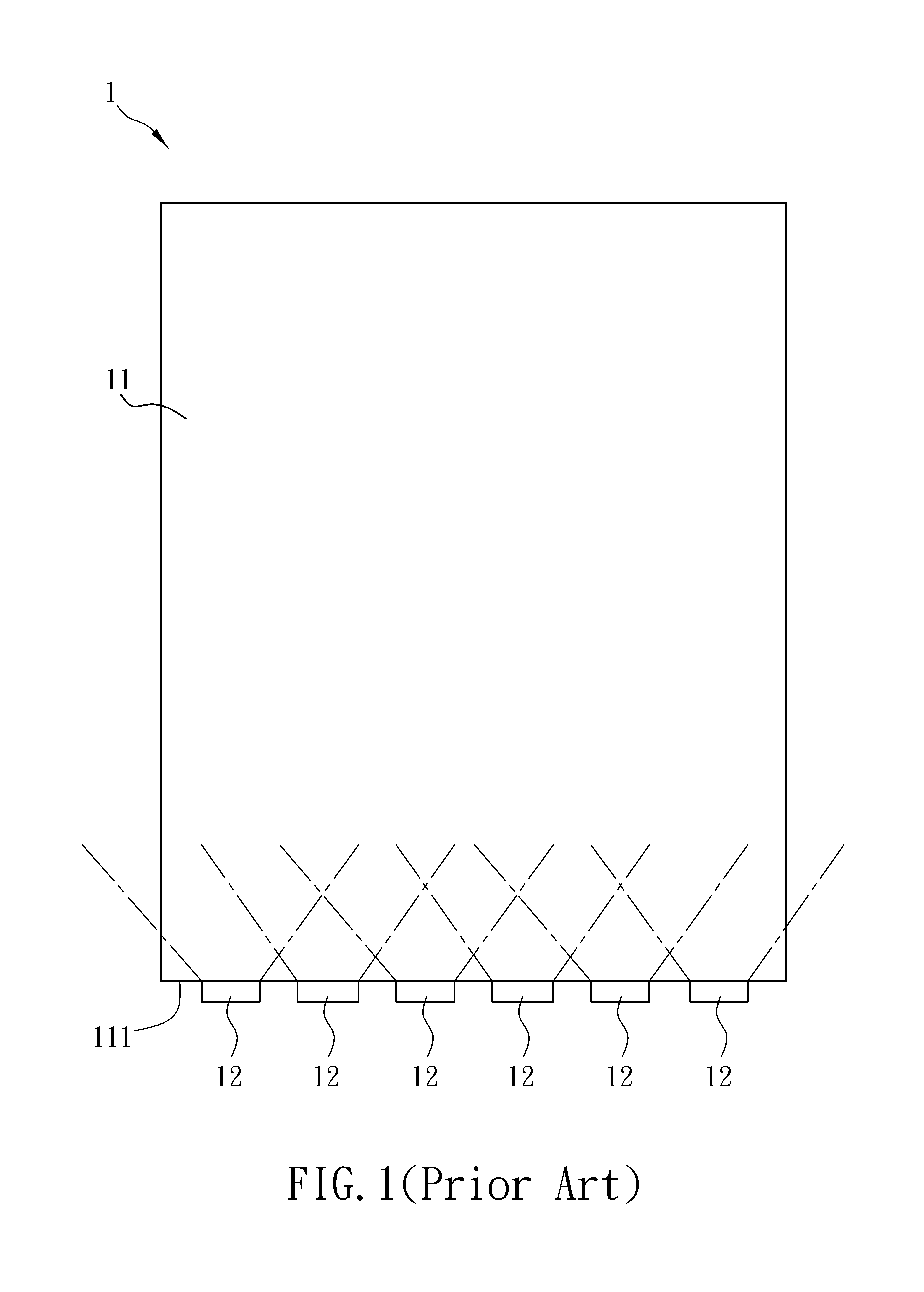
However, the high power LEDs have larger dimensions, so that a thickness of the light-guiding plate needs to be increased.
Unfortunately, such a requirement is not favorable for the demands of lightness and slimness of products.

Method used


Image

  • Lighting apparatus, backlight module and display apparatus
  • Lighting apparatus, backlight module and display apparatus
  • Lighting apparatus, backlight module and display apparatus

Examples


Embodiment Construction

[0023]The present invention will be apparent from the following detailed description, which proceeds with reference to the accompanying drawings, wherein the same references relate to the same elements.

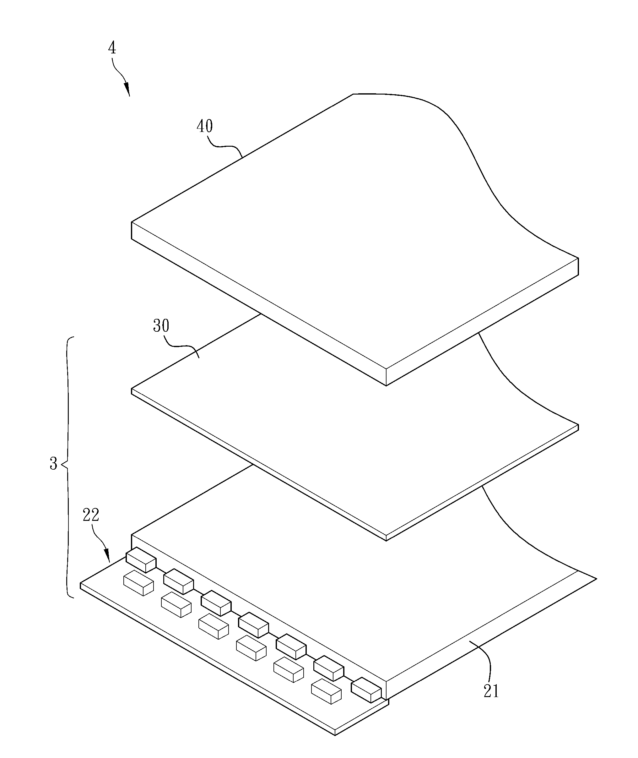
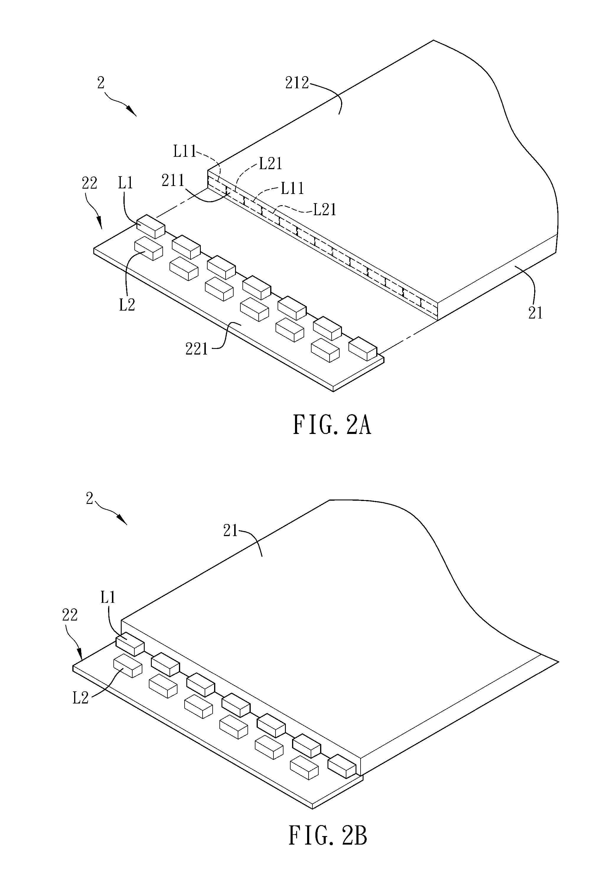
[0024]FIG. 2A is an exploded perspective view of a lighting apparatus 2 according to a preferred embodiment of the present invention, and FIG. 2B is an assembled perspective view of the lighting apparatus 2 in FIG. 2A. Referring to FIGS. 2A and 2B, the lighting apparatus 2 comprises a light-guiding plate 21 and a lighting unit 22. In this embodiment, the lighting apparatus 2 can be an illumination device, a traffic signal light or an advertising board.

[0025]The material of the light-guiding plate 21 is, for example but not limited to, polymethylmethacrylate (PMMA), polycarbonate (PC) or other optical materials with high light transmittance. The light-guiding plate 21 has a light-incident surface 211 and a light-emitting surface 212 adjacent to the light-incident surface 211. The light...


PUM


Abstract

A lighting apparatus includes a light-guiding plate and a lighting unit. The light-guiding plate includes a light-incident surface and a light-emitting surface. The lighting unit includes a first light source, a second light source and a circuit board. The first and second light sources are disposed on the circuit board, and the light emitted by the first and second light sources enters into the light-guiding plate through the light-incident surface and exits the light-guiding plate through the light-emitting surface. A first distance from the first light source to a reference line of the light-incident surface is not equal to a second distance from the second light source to the reference line.

Description

CROSS REFERENCE TO RELATED APPLICATIONS[0001]This Non-provisional application claims priority under 35 U.S.C. §119(a) on Patent Application No(s). 100124120 filed in Taiwan, Republic of China on Jul. 7, 2011, the entire contents of which are hereby incorporated by reference.BACKGROUND[0002]1. Field of Invention[0003]The present invention relates to a lighting apparatus, a backlight module and a display apparatus. In particular, the present invention relates to a lighting apparatus, a backlight module and a display apparatus with light-emitting diodes.[0004]2. Related Art[0005]Since the commercialization of light emitting diode (LED), it is widely applied in various products in everyday life such as home appliances as well as indicator lights and light sources of various apparatuses because of its characteristics of long life expectancy, low power consumption and low temperature generated. In the recent years, LED is also applied in backlight modules of flat panel display devices.[00...

Claims


Application Information

Patent Timeline
Patent Type & Authority Applications(United States)
IPC IPC(8): F21V8/00
CPCG02B6/002G02F1/13471G02B6/0068G02B6/0021
Inventor LIN, TSENG-HUNG
Owner INNOLUX CORP
Learn More