Endoscope operation section and endoscope

Inactive Publication Date: 2013-01-10
OLYMPUS MEDICAL SYST CORP
View PDF11 Cites 15 Cited by
  • Summary
  • Abstract
  • Description
  • Claims
  • Application Information

AI Technical Summary

Benefits of technology

[0014]An endoscope operation section according to an aspect of the present invention includes: an angle operation member for bending a bending portion provided in an insertion portion of an endoscope, the angle operation member being provided in an operation section body of the endoscope operation section provided at a proximal end of the insertion portion; a first switch button for performing first operation of the endoscope, the first switch button being provided in a first surface of the operation section body; and a second switch button for performing second operation of the endoscope, the second switch button being provided side by side with the first switch button in the first surface and positioned on a side distant from the angle operation member relative to the first switch button, wherein the second switch button is formed so as to have an outer diameter smaller than that of the first switch button, an outer circumferential side of the second switch button is covered by a sheathing member of the operation section body, and a projection portion is formed at a site of the sheathing member, the site facing the first switch button, on an outer circumference of the second switch button, the projection portion projecting toward a side away from the first surface relative to another site of the sheathing member on the outer circumference of the second switch button.

Problems solved by technology

However, where switch buttons are arranged side by side at the operation section, the operator who is operating the endoscope while viewing an endoscopic image picked up by the image pickup unit operates the buttons without viewing the operation section, causing the problem of, for example, a switch button that is different from a switch button for desired operation being pushed by a finger of the left hand, that is, a switch being mistakenly operated.

Method used


Image

  • Endoscope operation section and endoscope
  • Endoscope operation section and endoscope
  • Endoscope operation section and endoscope

Examples


Embodiment Construction

[0029]An embodiment of the present invention will be described below with reference to the drawings. It should be noted that the drawings are schematic ones and, e.g., the relationship between a thickness and a width of each member and the ratios in thickness between the respective members are different from actual ones, and it should be understood that the drawings include parts that are different in dimensional relationship and / or ratio from one another.

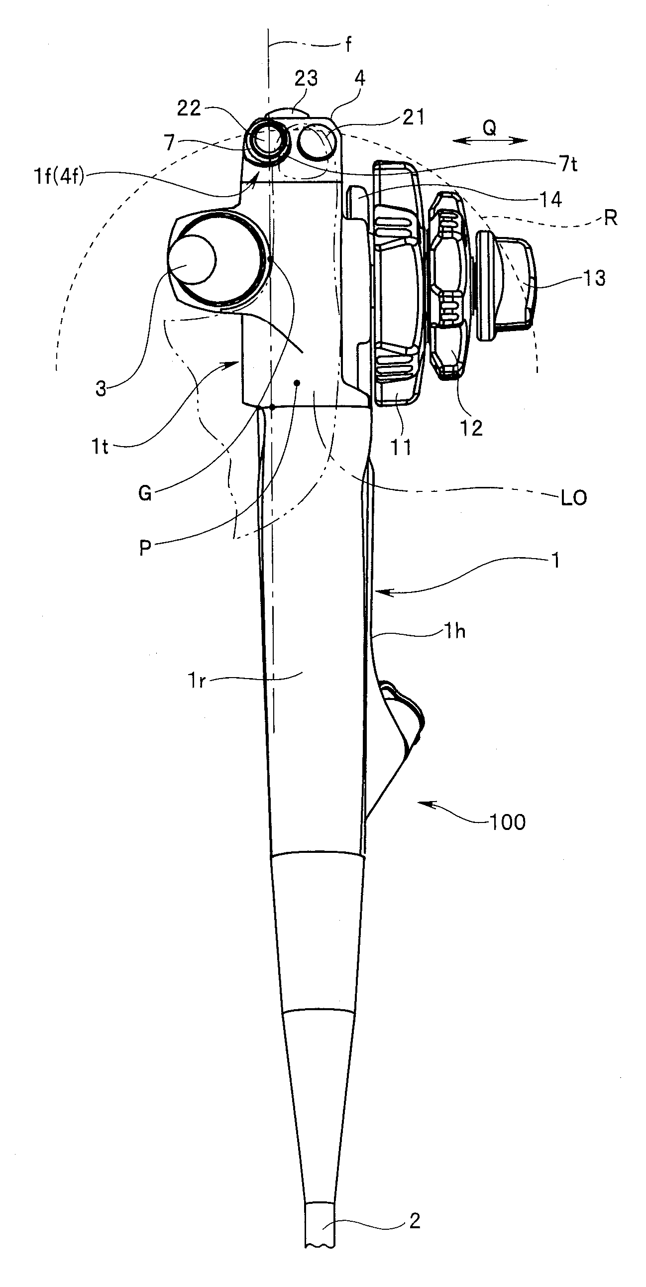
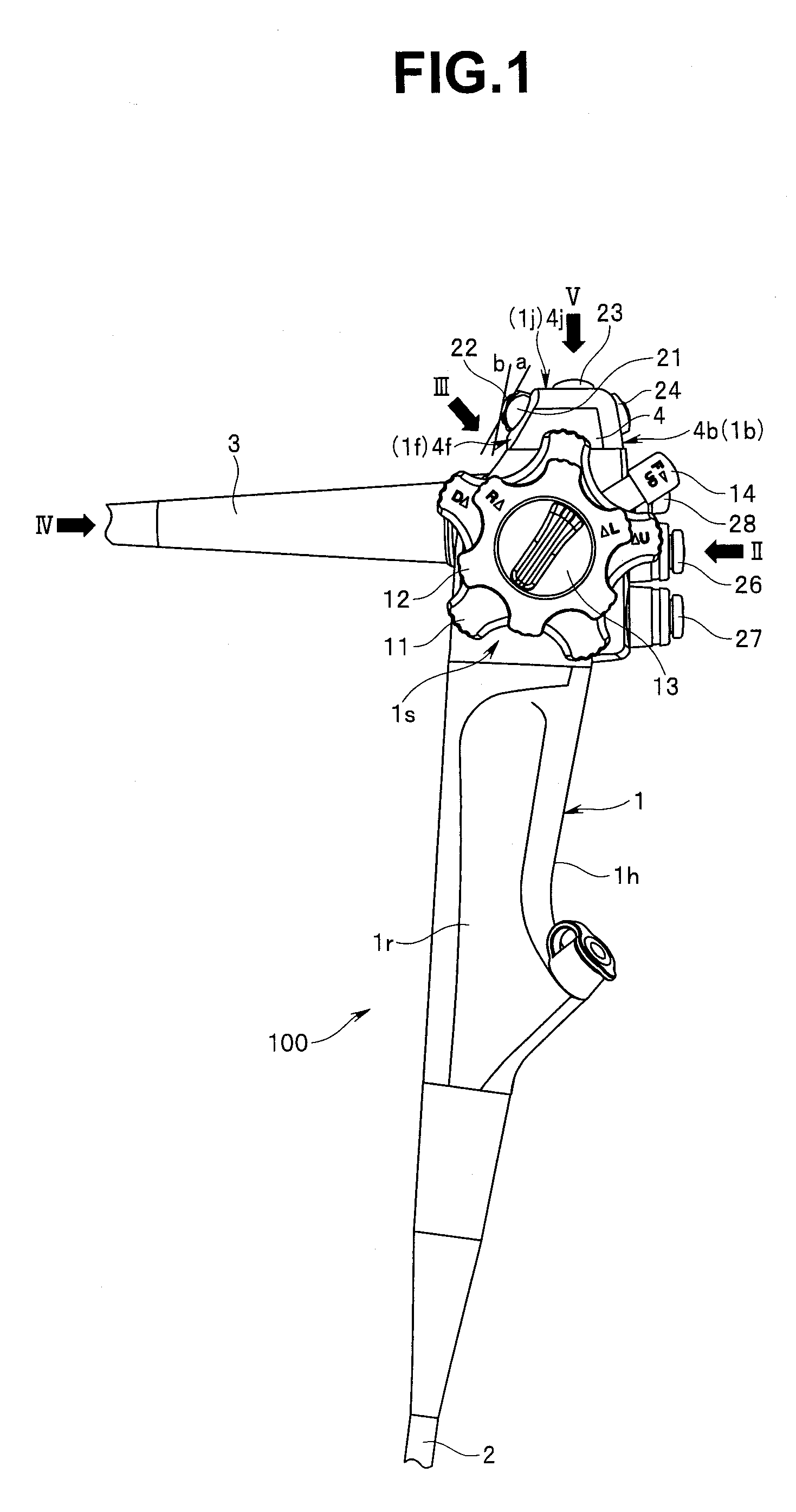
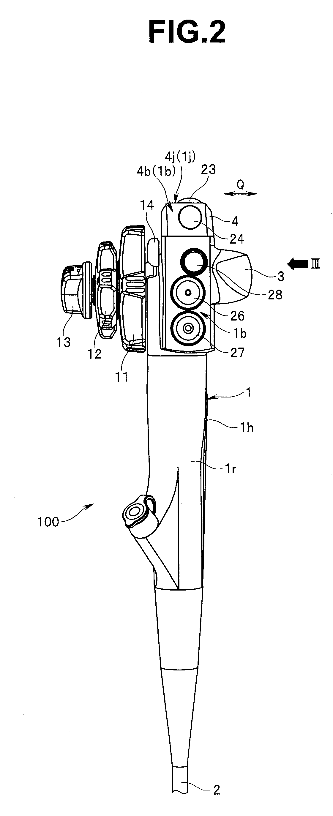
[0030]FIG. 1 is a partial perspective view of an endoscope including an endoscope operation section according to the present embodiment; FIG. 2 is a partial perspective view of the endoscope in FIG. 1 taken in the direction of arrow II in FIG. 1; FIG. 3 is a partial perspective view of the endoscope in FIGS. 1 and 2 taken in the direction of arrow III in FIGS. 1 and 2; FIG. 4 is a partial perspective view of the endoscope in FIG. 1 taken in the direction of arrow IV in FIG. 1; and FIG. 5 is a partial perspective view of the endosco...


PUM


Abstract

Bending operation knobs, a first switch button provided in a first surface, and a second switch button provided side by side with the first switch button in the first surface and positioned on the side distant from the bending operation knobs relative to the first switch button are included. The second switch button is formed so as to have an outer diameter smaller than that of the first switch button, an outer circumferential side of the second switch button is covered by a fitting portion, and a projection portion is formed at a site of the fitting portion, the site facing the first switch button, on an outer circumference of the second switch button, the projection portion projecting toward the side away from the first surface relative to another site of the fitting portion.

Description

CROSS REFERENCE TO RELATED APPLICATION[0001]This application is a continuation application of PCT / JP2011 / 058802 filed on Apr. 7, 2011 and claims benefit of Japanese Application No. 2010-096201 filed in Japan on Apr. 19, 2010, the entire contents of which are incorporated herein by this reference.BACKGROUND OF THE INVENTION[0002]1. Field of the Invention[0003]The present invention relates to an endoscope operation section provided at a proximal end of an insertion portion of an endoscope, and an endoscope.[0004]2. Description of the Related Art[0005]In recent years, endoscopes have widely been used in a medical field and an industrial field. With endoscopes used in the medical field, an elongated insertion portion is inserted into a body cavity, which is a subject, whereby an organ in the body cavity can be observed and as necessary various types of treatments can be performed using a treatment instrument inserted in a treatment instrument insertion channel included in the endoscope....

Claims


Application Information

Patent Timeline
Patent Type & Authority Applications(United States)
IPC IPC(8): A61B1/005
CPCA61B1/0052A61B1/00068G02B23/2476
Inventor NAKAMURA, NAOHIROOGURA, TAKESHI
Owner OLYMPUS MEDICAL SYST CORP
Why Eureka
Try Eureka