Materials for use in accommodating intraocular lens system
a technology for intraocular lenses and materials, applied in intraocular lenses, medical science, prosthesis, etc., can solve the problem that fixed focal length lenses lack the ability of natural lenses to dynamically move, and achieve the effect of reducing separation between viewing elements and greater relative movemen
- Summary
- Abstract
- Description
- Claims
- Application Information
AI Technical Summary
Benefits of technology
Problems solved by technology
Method used
Image
Examples
embodiment 250
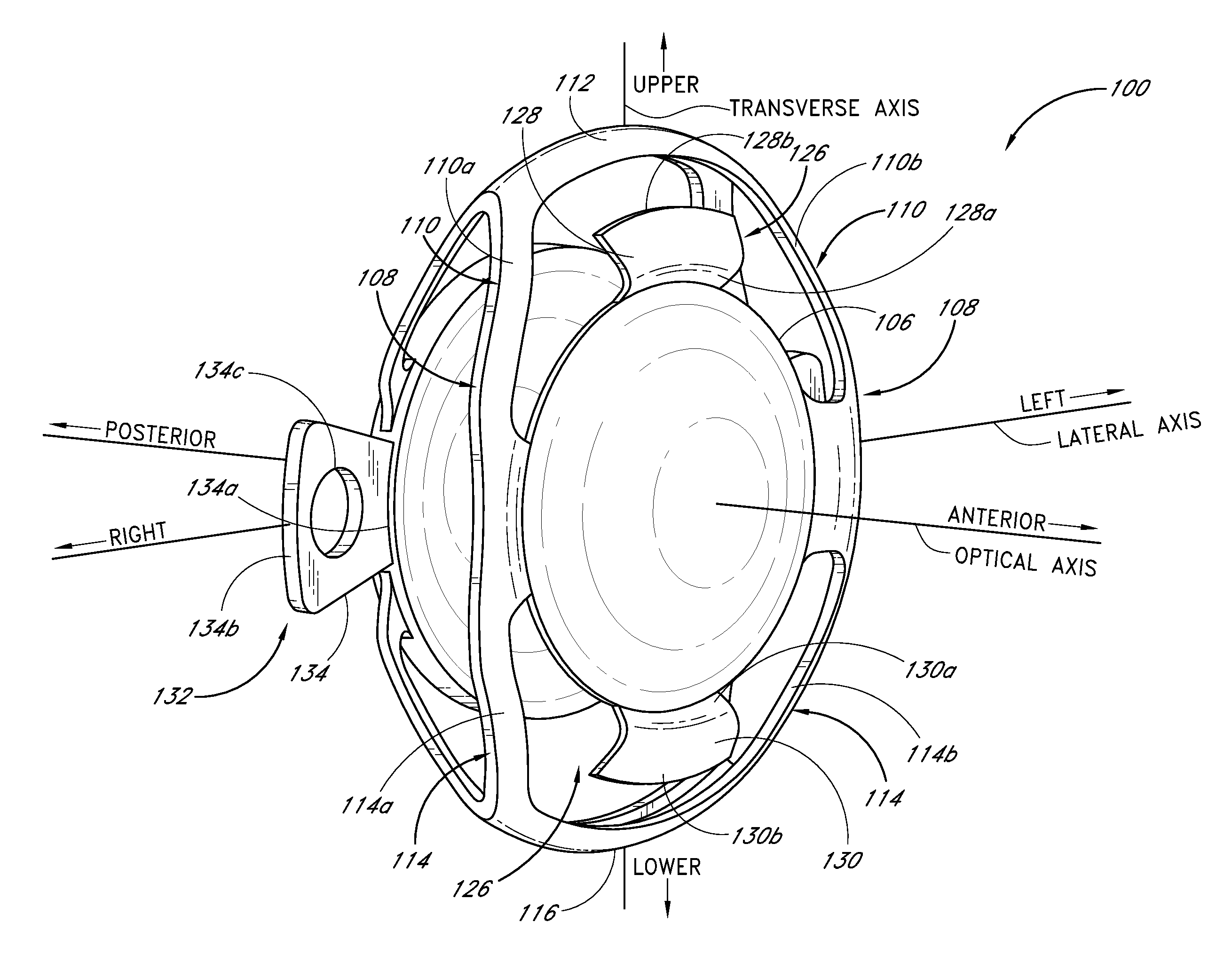
[0144]FIGS. 18 and 19 depict another embodiment 250 of the intraocular lens. It is contemplated that, except as noted below, this embodiment 250 is largely similar to the embodiment disclosed in FIGS. 3-17. The lens 250 features an anterior biasing element 108 and posterior biasing element 120 which are arranged asymmetrically as the lens system 100 is viewed from the side. As used herein to describe the biasing elements 108, 120, “asymmetric” or “asymmetrically” means that, as the lens system 100 is viewed from the side, the first anterior translation member 110 and the first posterior translation member 122 extend from the first apex 112 at unequal first anterior and posterior biasing angles δ1, δ2 with respect to the line B-B (which represents the edge of a plane which is substantially orthogonal to the optical axis and intersects the first and second apices 112, 116) and / or that the second anterior translation member 114 and the second posterior translation member 124 extend fro...
embodiment 600
[0204]FIG. 35 is a schematic view of a two-piece embodiment 600 of the lens system. In this embodiment the anterior portion 102 and the posterior portion 104 are formed as separate pieces which are intended for separate insertion into the capsular bag and subsequent assembly therein. In one embodiment, each of the anterior and posterior portions 102, 104 is rolled or folded before insertion into the capsular bag. (The insertion procedure is discussed in further detail below.) The anterior portion 102 and posterior portion 104 are represented schematically as they may generally comprise any anterior-portion or posterior-portion structure disclosed herein; for example, they may simply comprise the lens system 100 shown in FIGS. 3-17, bisected along the line / plane A-A shown in FIG. 4. The anterior portion 102 and posterior portion 104 of the two-piece lens system 600 will include first and second abutments 602, 604 which are intended to be placed in abutting relation (thus forming the ...
embodiment 800
[0207]FIGS. 37 and 38 show a further embodiment 800 of the lens system, in which the anterior and posterior biasing elements 108, 120 comprise integral “band” like members forming, respectively, the first and second anterior translation members 110, 114 and the first and second posterior translation members 122, 124. The biasing elements 108, 120 also form reduced-width portions 802, 804 which meet at the apices of the lens system 800 and provide regions of high flexibility to facilitate sufficient accommodative movement. The depicted distending portion 132 includes three pairs of distending members 134, 136 which have a curved configuration but nonetheless project generally away from the optical axis.
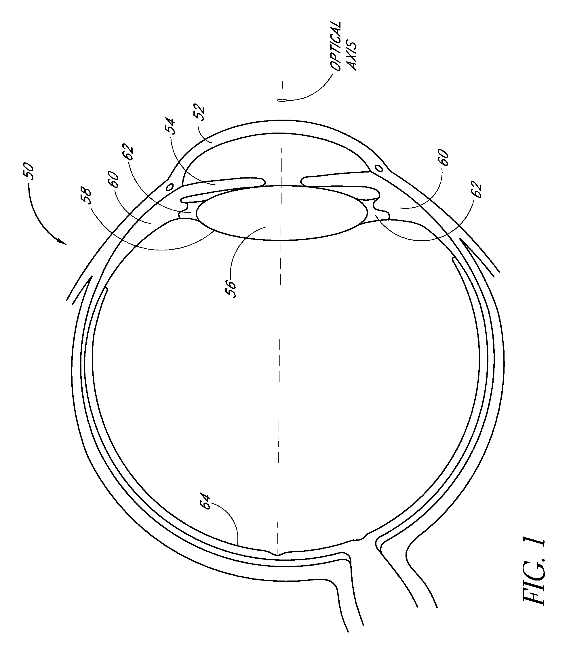
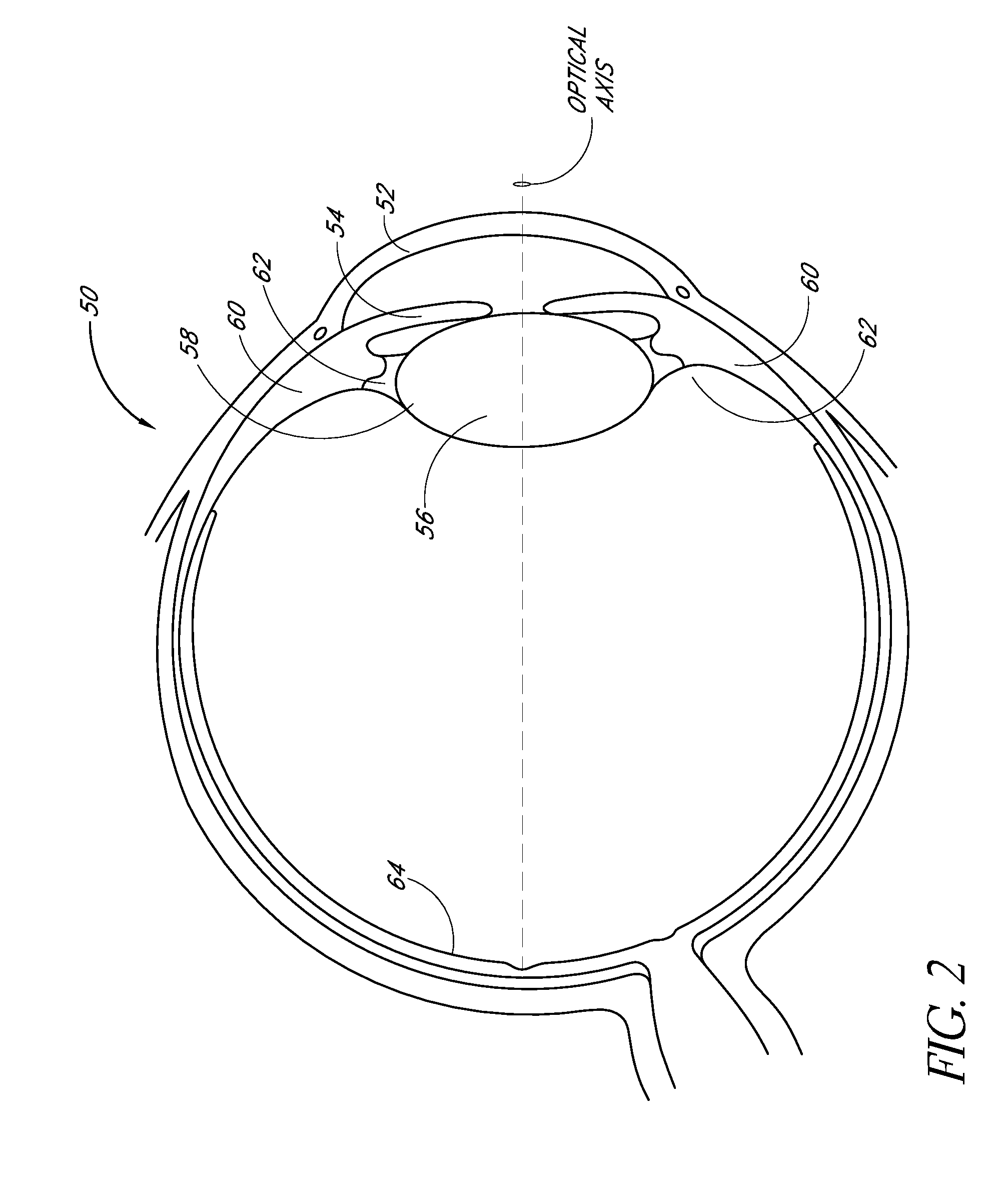
[0208]FIGS. 38A and 38B depict another embodiment 900 of the lens system, as implanted in the capsular bag 58. The embodiment shown in FIGS. 38A and 38B may be similar to any of the embodiments described above, except that the biasing elements 108, 120 are dimensioned so that the apice...
PUM
 Abstract
Description
Claims
Application Information
 - R&D
- Intellectual Property
- Life Sciences
- Materials
- Tech Scout
- Unparalleled Data Quality
- Higher Quality Content
- 60% Fewer Hallucinations
Browse by: Latest US Patents, China's latest patents, Technical Efficacy Thesaurus, Application Domain, Technology Topic, Popular Technical Reports.
© 2025 PatSnap. All rights reserved.Legal|Privacy policy|Modern Slavery Act Transparency Statement|Sitemap|About US| Contact US: help@patsnap.com


