Direct manipulation of composite terrain objects with intuitive user interaction

a composite terrain and user-friendly technology, applied in the field of computer-aided design applications, can solve the problems of difficult implementation of this concept, inability to provide an easy mechanism, and inability to achieve the effect of perfect earthwork balance, minimizing earthwork, and avoiding overlapping

Active Publication Date: 2013-01-10
AUTODESK INC
View PDF35 Cites 32 Cited by
  • Summary
  • Abstract
  • Description
  • Claims
  • Application Information

AI Technical Summary

Benefits of technology

[0083]Further, embodiments of the invention allow users to build a stepped parking lot with attached bounded planes with specified flow grades and directions, to direct drainage away from a building footprint and into the outfall points. Embodiments of the invention allow users to add fine details like sidewalks, retaining walls, curbs and gutters, whose dimensions can be edited interactively. The user is presented with simple workflows to create enhanced land features and modify them using 3D model interaction.
[0084]In addition, an important aspect of a cost-effective design is to obtain a perfect earthwork balance. A grading plan may have to go through several iterations before it yields an acceptable earthwork balance. As the design progresses, the cut and fill values must be adjusted to minimize the earthwork. Embodiments of the invention allow the user to attain the earthwork balance by raising or lowering specific areas of cuts or fills interactively until the desired level of precision is obtained. Such interaction may be performed in-canvas while directly modifying a composite object and / or sub-object in a dynamically updated terrain model. This allows the user to observe the impact of edits on many design aspects simultaneously (like drainage pattern, aesthetics) to build a cost-effective, sustainable design that balances all project requirements.

Problems solved by technology

These basic purposes often conflict with each other and prior art solutions fail to provide an easy mechanism to satisfy all of these purposes while utilizing a single grading model as the user proceeds from concept to completion of a project.
These goals often conflict with each other and to integrate them into the final design, they must be analyzed collectively.
This process can be very tedious.
The implementation of this concept is fraught with difficulties due to a variety of complex scenarios that could not be handled by a naïve ray projection algorithm, especially when projecting from curves with rapid elevation changes.
Such a methodology involves complex models whose history of operations is difficult to track.
The complexity of the existing solution results in difficult (if not impossible) software implementations that are error prone, unstable, and may completely fail (if supplied geometry is complicated).
Accordingly, users are hesitant to use the prior art product on account of such stability problems.
The prior art also provides few tools to modify existing solutions in an intuitive manner.
Further, the prior art fails to provide tools that can be used in a conceptual design that can also later be refined for generating production drawings.
The prior art provides a complex methodology that is neither natural nor user friendly.
This approach involves complex algorithms to solve inside corners and the intersection of overlapping solutions.
For example, the rapid transitions of offsets across the inside corners cause incomplete or failed 3D intersections of the adjacent, bounded planes.
However, stability problems and specialized functionality restrict the use of the prior art methods.
Thus, prior art solutions produce inside corners with complex geometry that is hard to clean, especially if the solutions involve degenerate partial solutions.
Solving such inside corners involves complex algorithms and is a cumbersome process.
In addition, when designing the drainage, the prior art fails to provide the ability to create or use organic shapes that could be used to produce an aesthetically pleasing landscape.
Moreover, there are few tools for modifying prior art solutions in ways that directly map to site development needs.
Even though there is a large set of elevation / grade editing tools, the overlapping line work can create difficult to resolve stability problems and elevation conflicts.
Predicting the impact of an edit to a solution requires experience, and factors like tessellation quality, crossing break lines, and Delaunay triangulation rules can confound a new user.
Accordingly, while prior art solutions may provide a model for visualizing and grading a terrain, such prior art models have various limitations.
For example, in prior art solutions, the history of the model cannot be viewed interactively, users cannot track the order of operations, and consequently, users may not be provided with the ability to understand how a model was built.
Such a lack of understanding gives rise to a communication gap across engineers working on the same project.
In addition, existing prior art models do not allow the user to click the model elements and modify them interactively in 3D.
Also, prior art models fail to provide a mechanism for modifying offsets and slopes interactively.
As described above, the existing solution does not allow the creation of a conceptual model that can later be refined into a more accurate model.
The prior art fails to provide such capabilities.

Method used


Image

  • Direct manipulation of composite terrain objects with intuitive user interaction
  • Direct manipulation of composite terrain objects with intuitive user interaction
  • Direct manipulation of composite terrain objects with intuitive user interaction

Examples


Embodiment Construction

[0033]In the following description, reference is made to the accompanying drawings which form a part hereof, and which is shown, by way of illustration, several embodiments of the present invention. It is understood that other embodiments may be utilized and structural changes may be made without departing from the scope of the present invention.

Overview

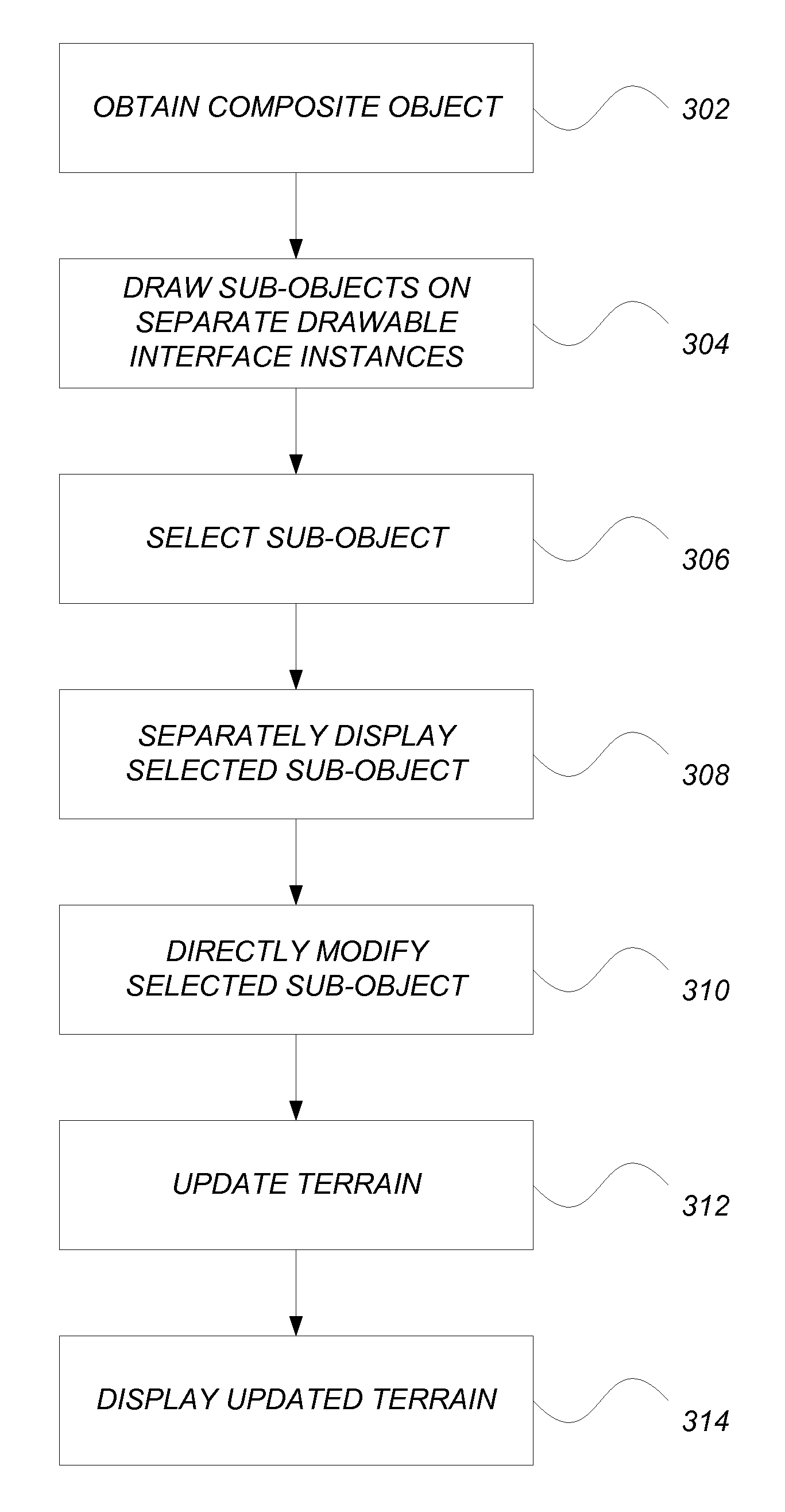
[0034]Embodiments of the invention provide direct manipulation capabilities to build, understand and modify a BIM CAD model.

Hardware Environment

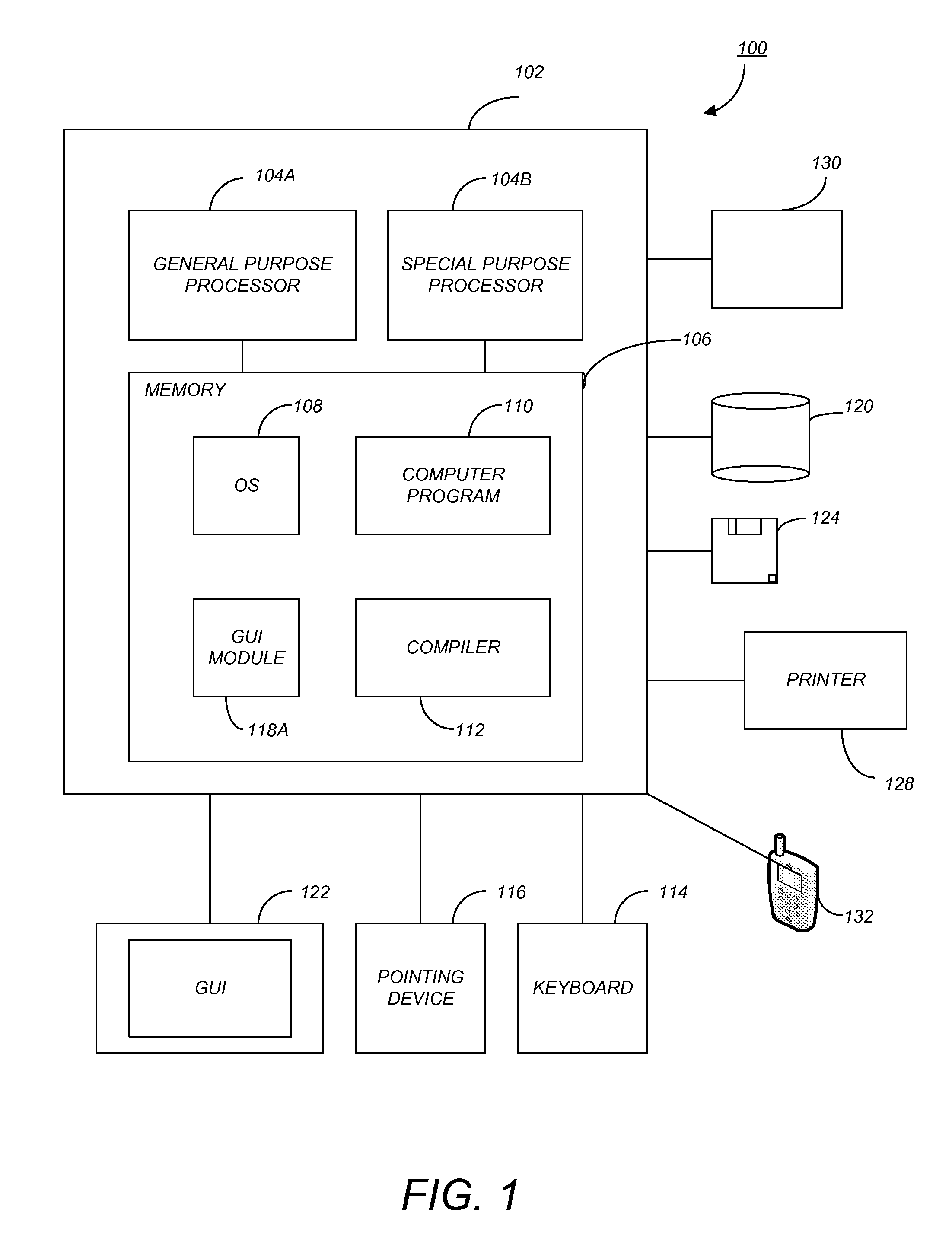
[0035]FIG. 1 is an exemplary hardware and software environment 100 used to implement one or more embodiments of the invention. The hardware and software environment includes a computer 102 and may include peripherals. Computer 102 may be a user / client computer, server computer, or may be a database computer. The computer 102 comprises a general purpose hardware processor 104A and / or a special purpose hardware processor 104B (hereinafter alternatively collectively referred to as processor 104)...


PUM


Abstract

A method, apparatus, system, and computer readable medium provide the ability to manipulate a terrain in a drawing. A composite object of the terrain is obtained in a CAD BIM application. The composite object is a combination of sub-objects that each define a geometry that is part of the terrain. Each of the sub-objects is drawn on a separate corresponding drawable interface instance. A sub-object is selected and in response, the selected sub-object is displayed in its corresponding drawable interface instance. The selected sub-object is directly modified, in canvas, using the drawable interface instance. In response to the modification, the terrain is dynamically updated and displayed.

Description

CROSS-REFERENCE TO RELATED APPLICATIONS[0001]This application is related to the following co-pending and commonly-assigned patent applications, which applications are incorporated by reference herein:[0002]U.S. patent application Ser. No. ______, entitled “GRADING METHOD UTILIZING FLOW GRADE SOLUTION”, by Smita Narayan and Christopher E. Putnam, et. al., Attorney Docket No. 30566.469-US-01, filed on the same date herewith; and[0003]U.S. patent application Ser. No. ______, entitled “INTERACTIVELY SHAPING TERRAIN THROUGH COMPOSABLE OPERATIONS”, by Smita Narayan and Christopher E. Putnam, et. al., Attorney Docket No. 30566.477-US-01, filed on the same date herewith; andBACKGROUND OF THE INVENTION[0004]1. Field of the Invention[0005]The present invention relates generally to computer aided design (CAD) applications, and in particular, to a method, apparatus, and article of manufacture for enabling, in a building information model (BIM) CAD application, direct manipulation techniques tha...

Claims


Application Information

Patent Timeline
Patent Type & Authority Applications(United States)
IPC IPC(8): G06F17/50
CPCG06T19/20G06F17/30241G06T17/05G06F3/04815G06F17/5009H04L41/22G06F30/20G06F16/29
Inventor NARAYAN, SMITAPUTNAM, CHRISTOPHER E.
Owner AUTODESK INC
Why Eureka
Try Eureka