
Container Having Multiple Compartments Containing Liquid Material for Multiple Wafer-Processing Chambers

a technology of liquid material storage and container, which is applied in the direction of liquid surface applicators, metal material coating processes, coatings, etc., can solve the problems of increasing the footprint of the multiple reactor platform, difficult to uniformly introduce vaporized liquid material to the multiple reactors at the same concentration, and easy to affect the quality of films, etc., to achieve the effect of reducing the footprint and the cost of the container

Inactive Publication Date: 2013-01-17
ASM JAPAN
View PDF5 Cites 349 Cited by
  • Summary
  • Abstract
  • Description
  • Claims
  • Application Information

AI Technical Summary

Benefits of technology

This patent describes a new design for a container used to process wafers. The design includes separate compartments for gas and liquid phases, which allows for a constant gas ratio and reduces the amount of carrier gas needed. This results in a more efficient and cost-effective design compared to conventional containers.

Problems solved by technology

In the multiple-reactor platform, the number of required liquid material containers is a product of the number of liquid materials used and the number of reactors, increasing the footprint of the multiple-reactor platform.
The reason that one liquid material container is required for one reactor is that if one liquid material container is shared by two or more reactors, it is difficult to uniformly introduce vaporized liquid material to the multiple reactors at the same concentration when splitting a gas flow into multiple gas flows upstream of the reactors or when sharing a carrier gas inlet for multiple gas outlets of the liquid material container.
Since the liquid material is a precursor constituting an element or elements of the main chemical structure of a film, if the quantity of vaporized liquid material taken by carrier gas from the liquid material container and introduced into the multiple reactors varies depending on the reactor even to a small degree, the quality of films is easily affected.

Method used


Image

  • Container Having Multiple Compartments Containing Liquid Material for Multiple Wafer-Processing Chambers
  • Container Having Multiple Compartments Containing Liquid Material for Multiple Wafer-Processing Chambers
  • Container Having Multiple Compartments Containing Liquid Material for Multiple Wafer-Processing Chambers

Examples


Embodiment Construction

[0031]In the disclosure, “liquid material” may refer to a material or materials which is / are normally in liquid form at room temperature under the standard atmospheric pressure. The liquid material may be a precursor which constitutes an element or elements of film to be deposited on a wafer. In this disclosure, “gas” may include vaporized solid and / or liquid and may be constituted by a mixture of gases. In this disclosure, the reactive gas, the additive gas, and the hydrogen-containing silicon precursor may be different from each other or mutually exclusive in terms of gas types, i.e., there is no overlap of gas types among these categories. Gases can be supplied in sequence with or without overlap.

[0032]In some embodiments, “film” refers to a layer continuously extending in a direction perpendicular to a thickness direction substantially without pinholes to cover an entire target or concerned surface, or simply a layer covering a target or concerned surface. In some embodiments, “...


PUM

PropertyMeasurementUnit
Flow rateaaaaaaaaaa
Dimensionaaaaaaaaaa
Energyaaaaaaaaaa

Abstract

A container for containing a liquid material for processing a wafer includes: a container body; a divider dividing the interior of the container body and defining compartments fluid-tightly sealed off from each other except for bottom portions of the compartments; gas inlet ports for introducing gas to the respective compartments and gas outlet ports for discharging gas from the respective compartments; and a liquid level sensor provided in one of the compartments for keeping a liquid surface of a liquid material above the bottom portions when the container is in use conditions.

Description

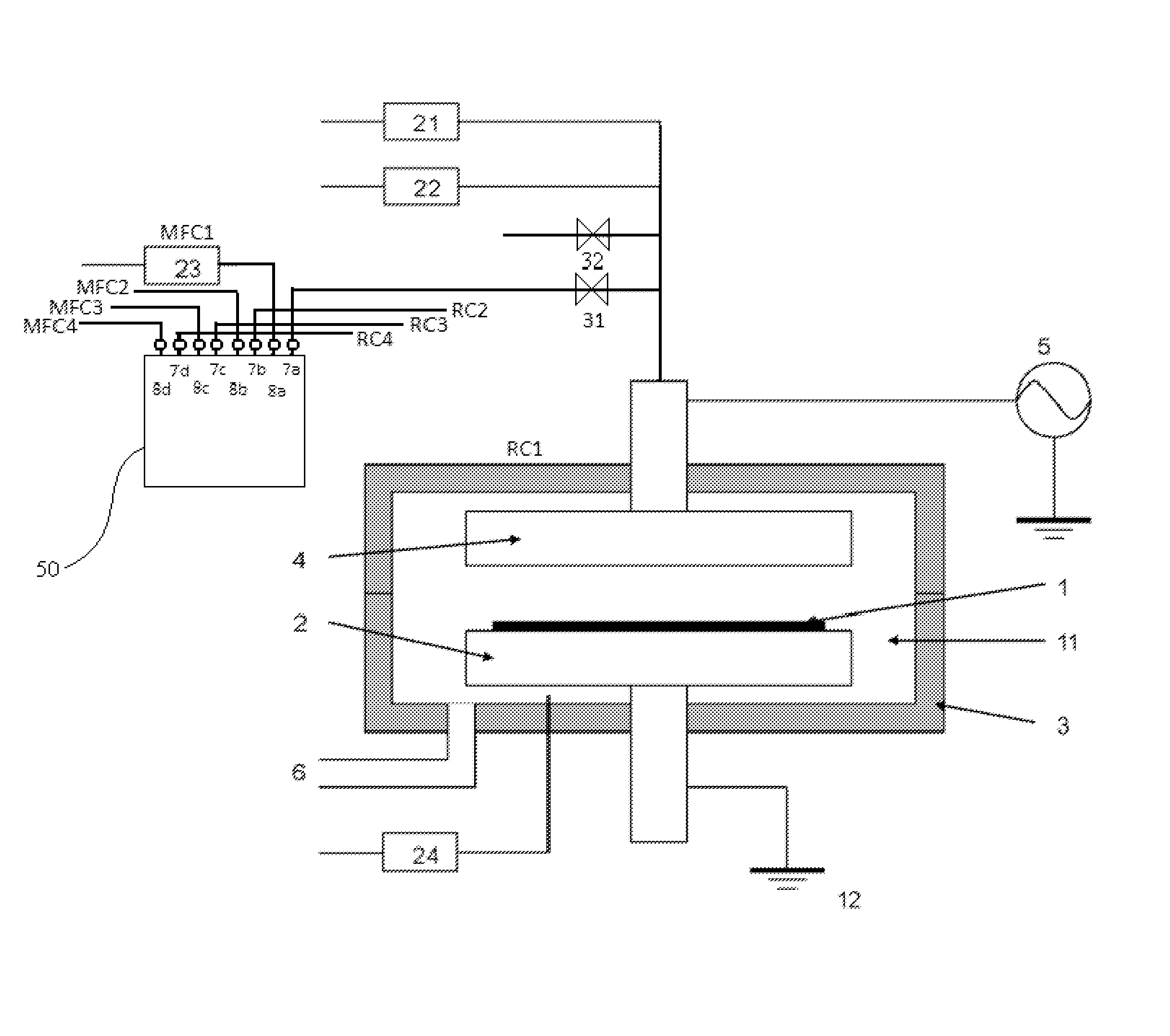
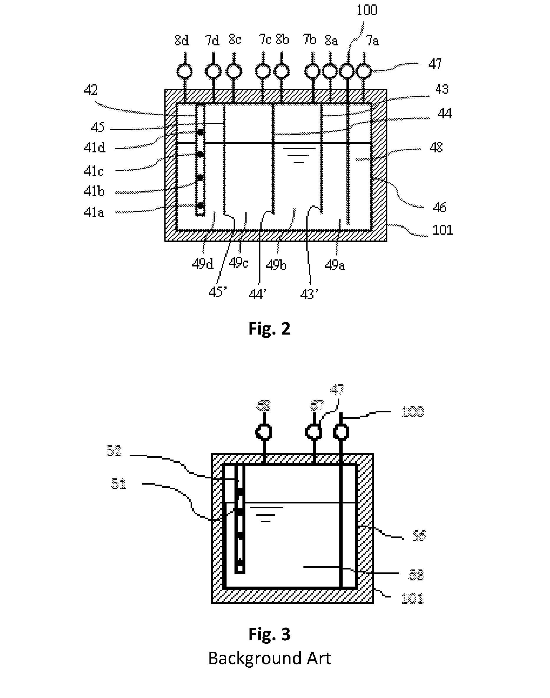
BACKGROUND OF THE INVENTION[0001]1. Field of the Invention[0002]The present invention generally relates to a container for storing a liquid material for processing a wafer, particularly to such a container for supplying gas of the liquid material to multiple reactors.[0003]2. Description of the Related Art[0004]Conventionally, to use one liquid material as a precursor, one liquid material container storing the liquid material is required for one reactor for CVD or ALD. Thus, if there are multiple reactors, the same number of liquid material containers as that of the reactors is required. Further, if multiple liquid materials are used for processing, the same number of liquid material containers as that of the liquid materials is required. FIG. 3 is a schematic view of a container for storing a liquid material. A container body 56 enclosed by a precursor bottle heater 101 stores a liquid material 58 supplied thereto through a charge port 100 and is provided with a gas inlet port 68 a...

Claims


Application Information

Patent Timeline
IPC IPC(8): C23C16/455C23C16/52C23C16/50
CPCC23C16/4481
Inventor KANAYAMA, HIROKI
Owner ASM JAPAN
Learn More