Toroidal Combustion Chamber With Side Injection

a side injection and combustion chamber technology, applied in the direction of combustion engines, positive displacement engines, oscillating piston engines, etc., can solve the problem of less known about the shape and fuel of the combustion chamber

Inactive Publication Date: 2013-01-17
ACHATES POWERS INC +1
View PDF4 Cites 36 Cited by
  • Summary
  • Abstract
  • Description
  • Claims
  • Application Information

AI Technical Summary

Problems solved by technology

However, in unconventional engines, less is known about what combustion chamber shape and fuel injection characteristics can provide the desired mixing and engine performance.

Method used


Image

  • Toroidal Combustion Chamber With Side Injection
  • Toroidal Combustion Chamber With Side Injection
  • Toroidal Combustion Chamber With Side Injection

Examples


Embodiment Construction

[0018]As those of ordinary skill in the art will understand, various features of the embodiments illustrated and described with reference to any one of the Figures may be combined with features illustrated in one or more other Figures to produce alternative embodiments that are not explicitly illustrated or described. The combinations of features illustrated provide representative embodiments for typical applications. However, various combinations and modifications of the features consistent with the teachings of the present disclosure may be desired for particular applications or implementations. Those of ordinary skill in the art may recognize similar applications or implementations whether or not explicitly described or illustrated.

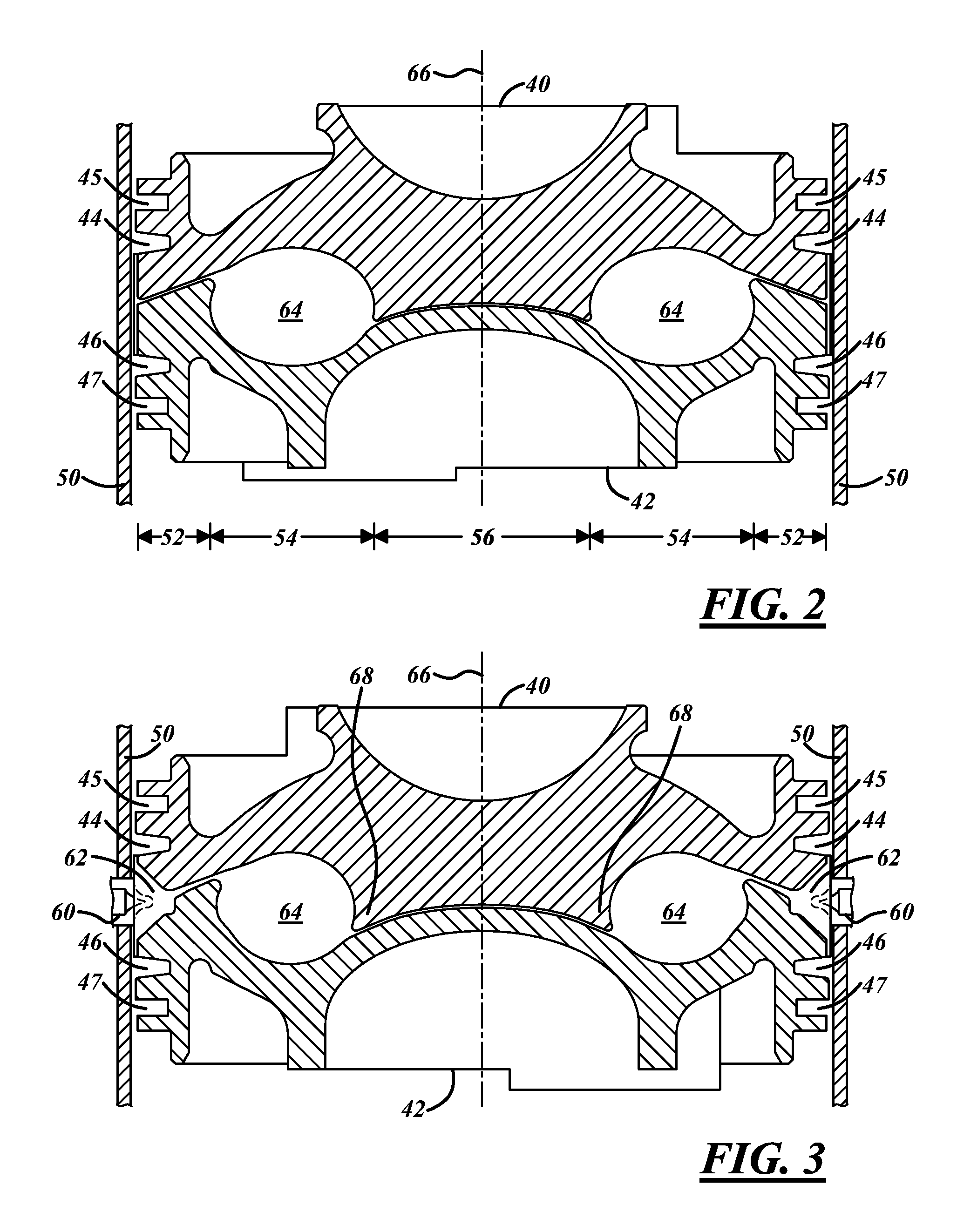
[0019]In FIG. 2, a cross section of a portion of an OPOC engine is shown illustrating a combustion chamber according to an embodiment of the disclosure. A portion of intake piston 40 and a portion of exhaust piston 42 are shown at their closest positio...


PUM


Abstract

A toroidal combustion chamber shape with a side injector is disclosed for an opposed-piston engine. Fuel is injected into the toroidal volume from a fuel injector in the cylinder wall. In one embodiment, fuel is injected from each injector a plurality of times with the timing between the injections such that fuel clouds from each injection remain substantially isolated from each other.

Description

CROSS REFERENCE TO RELATED APPLICATIONS[0001]The present application claims priority benefit from U.S. provisional patent application 61 / 508,151 filed 15 Jul. 2011.FIELD[0002]The present disclosure relates to shape of the combustion chamber and injector orientation in internal combustion engines.BACKGROUND[0003]Thermal efficiency and engine-out emissions from an internal combustion engine are determined by many factors including the combustion system design and the mechanical design. Combustion system design includes combustion chamber shape, the fuel injection nozzle, and the fuel injection pressure, intake manifold and exhaust manifold, etc. All of these together are optimized to achieve mixing quality that leads to effective combustion. Much is known and much has been studied in typical diesel engine combustion systems to determine what chamber shape and fuel injection characteristics lead to the desired output. However, in unconventional engines, less is known about what combust...

Claims


Application Information

Patent Timeline
Patent Type & Authority Applications(United States)
IPC IPC(8): F01C9/00
CPCF02B23/0663F02B23/0675Y02T10/125F02B75/282F01B7/08Y02T10/12F01B1/08F01B7/02F01B9/02F02B75/243F02B75/28
Inventor SHEN, HUIXIANHOFBAUER, PETER
Owner ACHATES POWERS INC
Why Eureka
Try Eureka