Relief device for oil pump

a technology for a relief device and an oil pump, which is applied in the direction of machines/engines, liquid fuel engines, and positive displacement liquid engines, etc., can solve the problems of unexpectedly low oil pressure, and achieve the effects of low cost, easy assembly, and simple configuration

Active Publication Date: 2013-01-17
HONDA MOTOR CO LTD +1
View PDF4 Cites 6 Cited by
  • Summary
  • Abstract
  • Description
  • Claims
  • Application Information

AI Technical Summary

Benefits of technology

[0015]According to the first aspect of the invention, the oil relief is performed within a range from the low-revolution region to the medium-revolution region of the engine, the relief is stopped within a range from the medium-revolution region to the high-revolution region, and the appropriate oil pressure can be maintained at each revolution speed of the engine. Further, an unstable state in which the oil pressure drops rapidly from the normal state in each revolution region can be prevented. In addition, although the device in accordance with the present invention demonstrates the abovementioned effect, the device can have a very simple configuration, can be easily assembled, and can be provided at a low cost.
[0016]According to the second aspect of the invention, the auxiliary recess is formed in addition to the main recess. As a result, the circulation amount of oil in the recess in the low-revolution region to medium-revolution region can be increased. Thus, by increasing or decreasing the volume of the auxiliary recess, it is possible to adjust easily the pressure in the low-revolution region to medium-revolution region. Furthermore, since the main recess and auxiliary recess can be easily formed in a linear shape by using a casting pin, low cost production is realized.
[0017]In accordance with the third aspect of the invention, the recess is formed as a narrow hole extending in the axial direction and having a small thickness in the circumferential direction. As a result, oil circulation can be performed in the recess in a revolution region wider than that in the case where the spring strength is adjusted. Since the revolution region in which the oil circulation is performed can be expanded or contracted by changing the axial length of the recess, a very fine pressure control can be performed as desired. In accordance with the fourth aspect of the invention, because of the configuration in which the widthwise dimension of the aforementioned recess is less than the diameter of the aforementioned valve passage portion and the recess is formed as a groove in the circumferential portion in the inner circumferential surface of the valve passage portion, it is possible to set a low amount of relief oil in the relief operation in a range from the low-revolution region to the medium-revolution region and rapid decrease in the oil pressure can be prevented.

Problems solved by technology

The resultant problem is that in the high-revolution region of the engine, the oil pressure unexpectedly becomes too low.

Method used


Image

  • Relief device for oil pump
  • Relief device for oil pump
  • Relief device for oil pump

Examples


Embodiment Construction

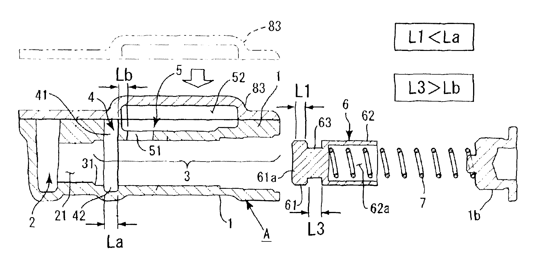
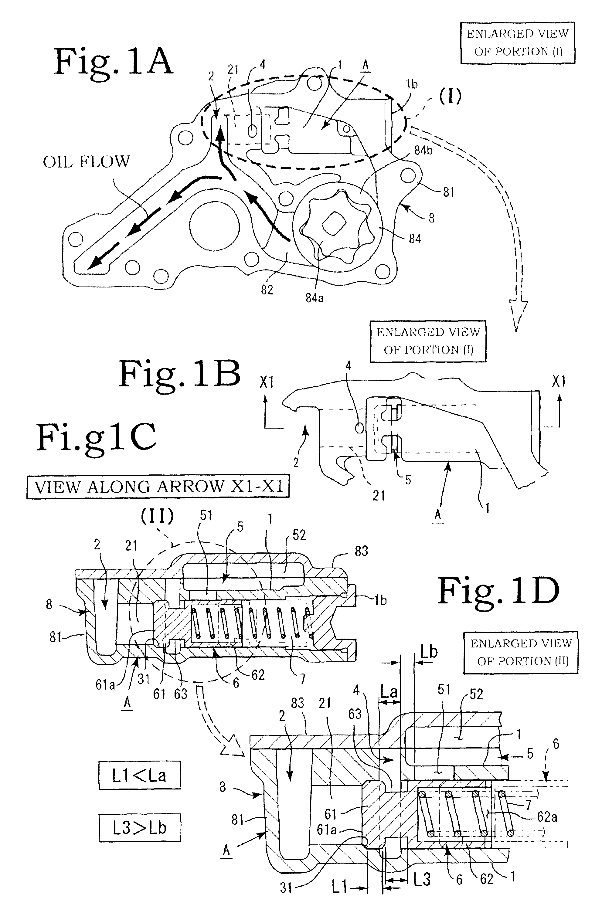
[0028]Embodiments of the present invention are described below with reference to the appended drawings. As shown in FIG. 1, the relief device in accordance with the present invention is mainly constituted by a relief housing A, a relief valve 6, and a spring 7. The relief housing A is integrally formed inside a main body portion 81 of a pump body 8 of a mechanically driven oil pump 84 that supplies oil to an engine. The oil pump 84 is of an internal-engagement gear type, more specifically a toroidal gear pump constituted by an inner rotor 84a and an outer rotor 84b. The oil pump 84 is disposed in an appropriate location inside an engine room.

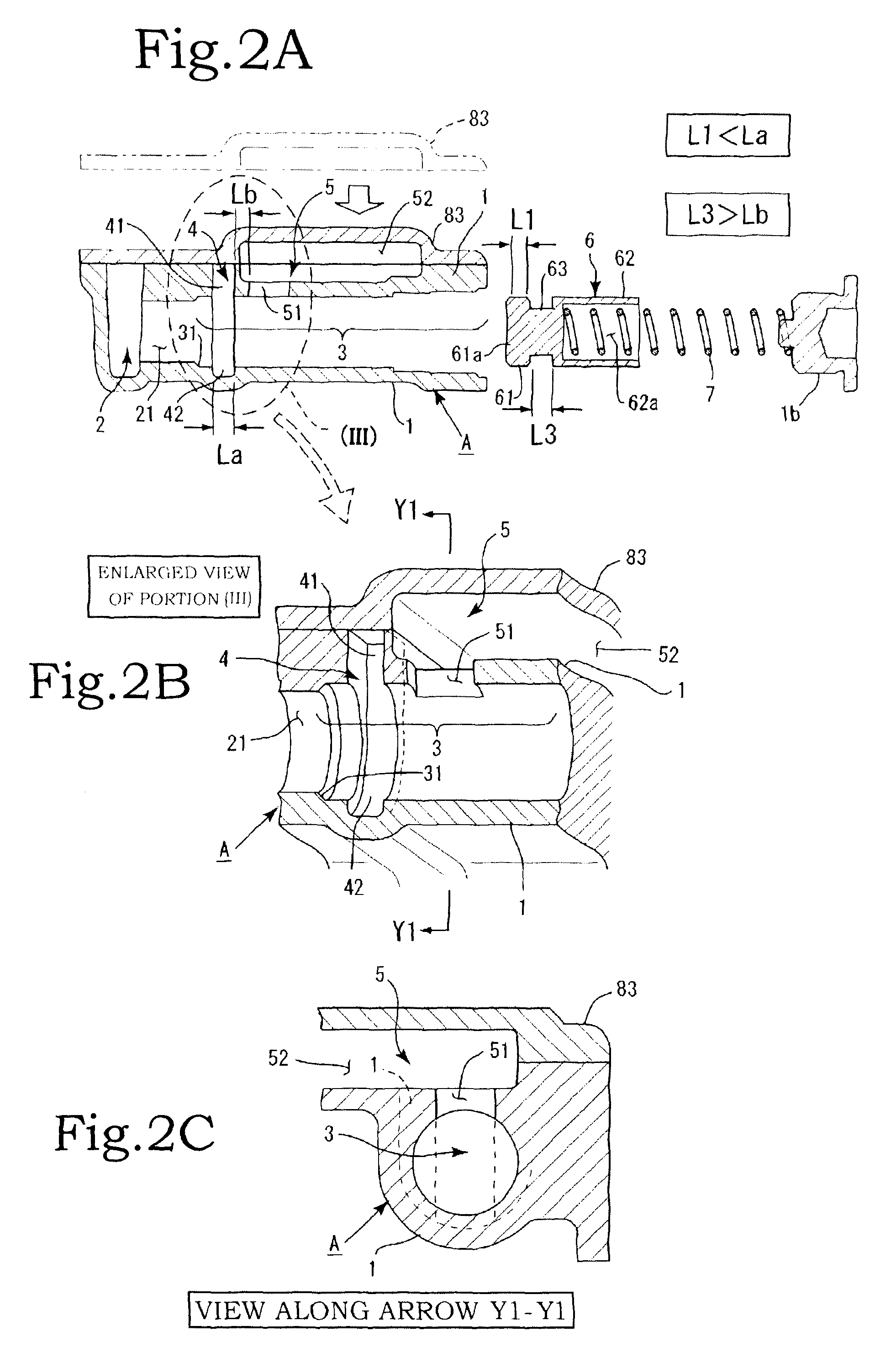
[0029]The relief housing A is formed as a tunnel of a substantially hollow cylindrical shape on the downstream side of a discharge flow channel 82 of the oil pump 84 formed inside the pump body 8. The relief housing A is constituted by a cover portion 1, a relief inflow portion 2, and a valve passage portion 3 (FIGS. 1A, 1B, and 2). The cover po...


PUM


Abstract

A relief device includes a relief housing constituted by a relief inflow portion, a valve passage portion, a recess, and an oil discharge portion having a relief hole; a relief valve having a small-diameter portion between a first large-diameter portion and a second large-diameter portion; and a spring elastically biasing the relief valve toward the relief inflow portion. The recess is formed at a position that is closer to the relief inflow portion side than to the oil discharge portion, the axial length of the recess is larger than the axial length of the first large-diameter portion of the relief valve, and the shortest axial distance between the recess and the relief hole is less than the axial length of the small-diameter portion.

Description

BACKGROUND OF THE INVENTION[0001]1. Field of the Invention[0002]The present invention relates to a relief device for an oil pump that can ensure an appropriate pressure of oil discharged from the oil pump in a high-revolution region of an engine, ensure good lubrication ability in a medium-revolution region, and improve the efficiency of the engine.[0003]2. Description of the Related Art[0004]A relief valve is often installed, downstream of an oil pump, as a device for preventing an excessive increase in the discharge pressure of the oil pump. The conventional relief valves have a function of protecting the flow channel and devices located thereon from an extremely high oil pressure, but in recent years the emphasis has been placed on reduction of ineffective operations of the oil pump by the adjustment of oil pressure to the intended value in order to reduce fuel consumption.[0005]The relief valves as means for adjusting the discharge pressure of oil pumps in order to realize the a...

Claims


Application Information

Patent Timeline
Patent Type & Authority Applications(United States)
IPC IPC(8): F16K15/00
CPCF01M1/16F04B49/08F04C2210/206F04C2/10F04C14/26Y10T137/7845Y10T137/7929Y10T137/7867Y10T137/7925
Inventor AKAISHI, NOBUYUKIIKAWA, MASATAKAUETA, YASUHIROISHIOKA, TAKUJIKAMIYAMA, HIDEHIKOYAMAZAKI, TAKUYAUMEZAWA, YOSHIROINOUE, HIROKAZUKUROKAWA, YOSHITAKA
Owner HONDA MOTOR CO LTD
Why Eureka
Try Eureka