Device for filtering liquids

Active Publication Date: 2013-01-17
PANTREON
View PDF2 Cites 8 Cited by
  • Summary
  • Abstract
  • Description
  • Claims
  • Application Information

AI Technical Summary

Benefits of technology

[0018]For a further improvement of the flow picture prevailing on the filter elements in a desired direction, the filter elements can be trapezoidal discs. This has the advantage that the undesired excess clearance between adjacent filter elements can be decreased and the effective usable filter area in a device can be increased. In order that only one filter shape has to be used, which is similarly suitable for smaller and larger paths to be implemented leading around the container axis, a trapezoidal shape is preferable, in the case of which the lateral end flanks of the filter elements are not consistently i

Problems solved by technology

The main problem in the membrane filtration of liquids, namely the formation of cover layers on the membrane surface and the shrinkage of the effective filter area and blocking of the membrane pores thus caused, is therefore prevented or reduced.
However, during a rotation of large horizontally aligned filter surfaces with incident flow, e

Method used


Image

  • Device for filtering liquids
  • Device for filtering liquids
  • Device for filtering liquids

Examples


Example

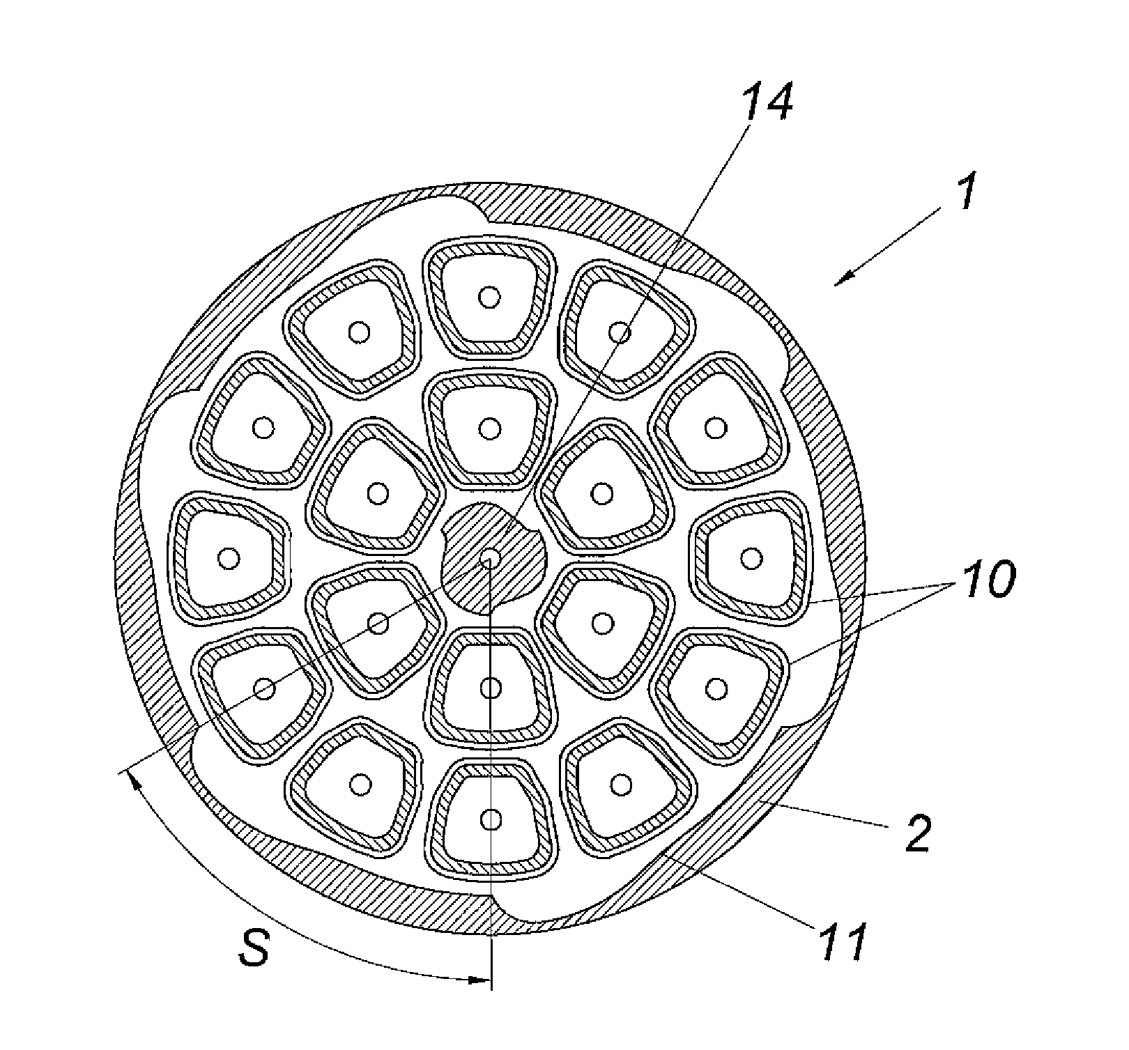
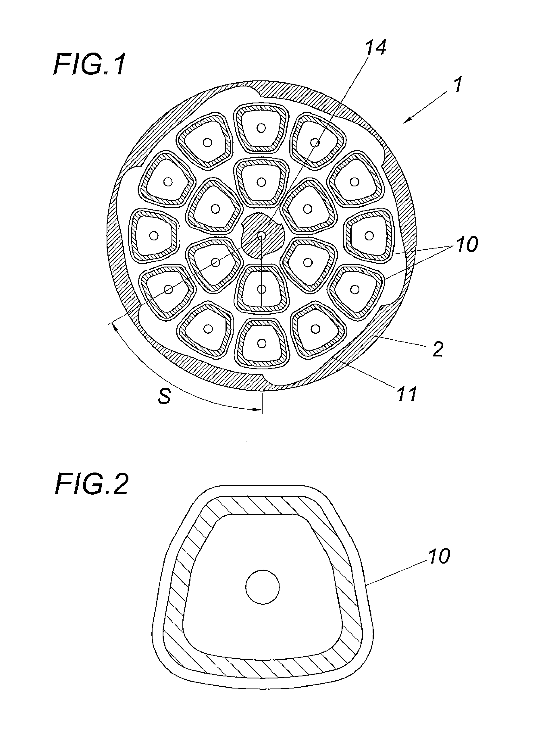
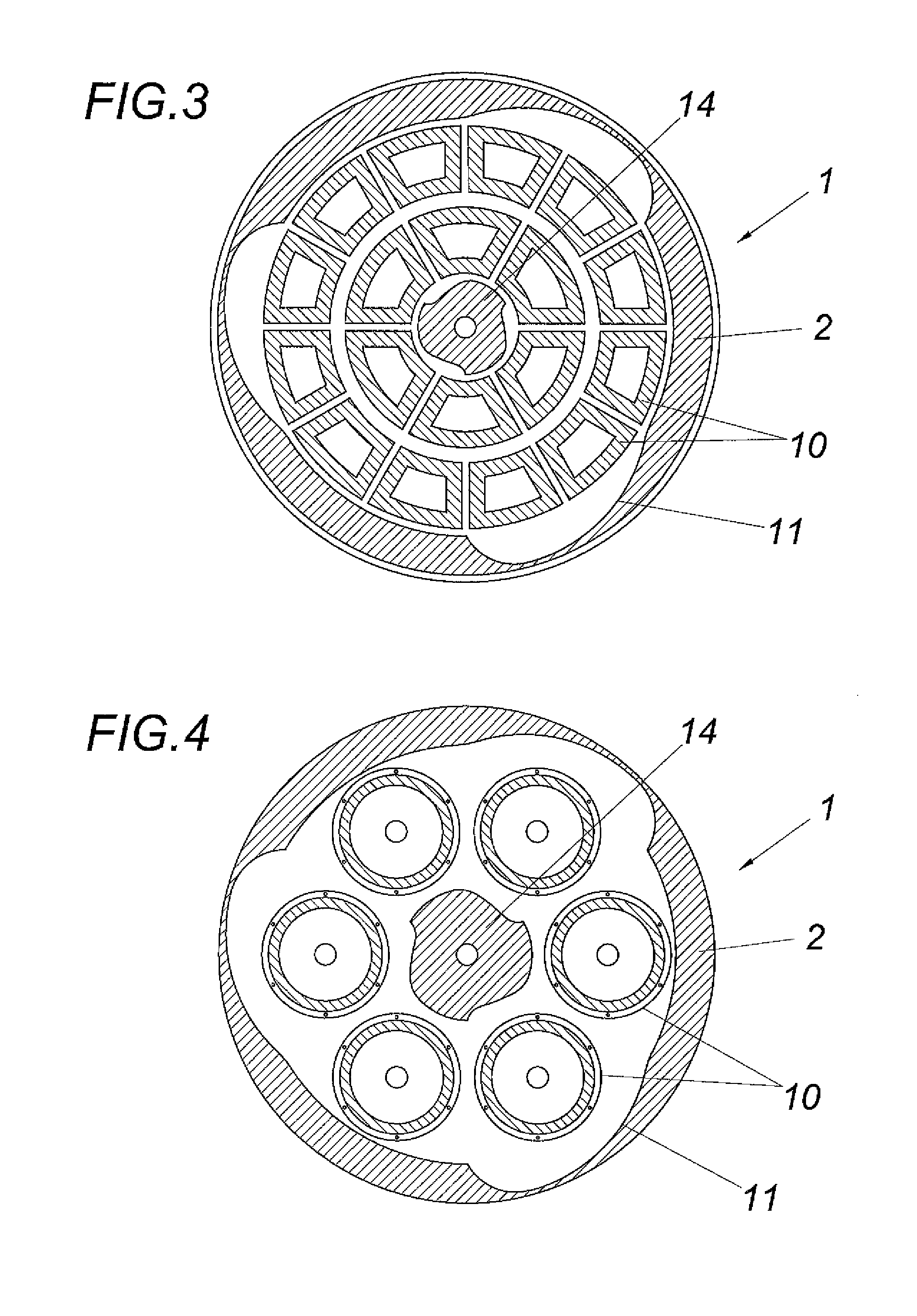
[0030]A device 1 for filtering liquids comprises a container 2, units (not shown in greater detail) for introducing a liquid to be filtered into the container 2, which is typically introduced into the container 2 in the region of the container floor, a container outlet 4 for unfiltered liquid to be discharged from the container 2, and a rotor 6, which is drivable to rotate around the container axis 5, having a hollow shaft 8 mounted in the bottom end wall 7 and a support device 9 fastened thereon for filter elements 10, which are arranged with radial spacing to the container axis 5. The interior of the filter elements 10 opens via the support device 9 and the hollow shaft 8 out of the container 2 as the discharge for filtered liquid. Unfiltered liquid is conducted into the container outlet 4 via the outlet opening 12.

[0031]According to the invention, the container shell 11 is formed in such a manner that the container internal radius 12 of the inner wall 11 of the container circumfe...


PUM

PropertyMeasurementUnit
Speedaaaaaaaaaa
Radiusaaaaaaaaaa

Abstract

The invention relates to a device (1) for filtering liquids, having a container (2), units (3) for introducing a liquid to be filtered into the container (2), a container outlet (4) for unfiltered liquid to be discharged from the container (2), and at least one rotor (6), which is drivable to rotate around the container axis (5), having a hollow shaft (8) mounted in an end wall (7) and a support device (9) fastened thereon for filter elements (10), which are arranged with a clearance to the container axis (5) or rotate around their own axis, and whose interior opens via the support device (9) and the hollow shaft (8) out of the container (2) as the discharge for filtered liquid. To provide improved filtration conditions, it is proposed that the container internal radius (12) of the inner wall of the container circumferential shell (11) is enlarged up to a maximum in the container circumferential direction while bulging the inner wall between two minima, this bulge forming a guide unit which guides the liquid toward the filter elements (10).

Description

FIELD OF THE INVENTION[0001]The invention relates to a device for filtering liquids, having a container, units for introducing a liquid to be filtered into the container, a container outlet for unfiltered liquid to be discharged from the container, and at least one rotor, which is drivable to rotate around the container axis, having a hollow shaft mounted in an end wall and a support device fastened thereon for filter elements, which are arranged with a clearance to the container axis or rotate around their own axis, and whose interior opens via the support device and the hollow shaft out of the container as the discharge for filtered liquid.DESCRIPTION OF THE PRIOR ART[0002]Such known devices (EP 577 854 B1) comprise a rotor as a stirring body, whose stirring elements are formed by tubular filter elements with vertical incident flow. The main problem in the membrane filtration of liquids, namely the formation of cover layers on the membrane surface and the shrinkage of the effectiv...

Claims


Application Information

Patent Timeline
IPC IPC(8): B01D33/31
CPCB01D33/31B01D35/30B01D2315/02B01D2201/62B01D2313/20B01D63/16
Inventor LUER, ANDREAS
Owner PANTREON
Why Eureka
Try Eureka