Wind turbine cooling arrangement

a cooling arrangement and wind turbine technology, applied in the direction of electric generator control, machines/engines, mechanical equipment, etc., can solve the problems of limiting cooling capacity, active cooling is associated with costly machinery, etc., and achieve the effect of improving the cooling arrangemen

Inactive Publication Date: 2013-01-17
SIEMENS AG
View PDF7 Cites 10 Cited by
  • Summary
  • Abstract
  • Description
  • Claims
  • Application Information

AI Technical Summary

Benefits of technology

[0005]It is an object to provide an improved cooling arrangement.

Problems solved by technology

However, since heat is essentially always generated by components of a wind turbine, even if the rotor blades are not turning, so that energy is essentially always required to power active cooling components such as pumps, compressors, ventilators etc.
Furthermore, such active cooling is associated with costly machinery such as pumps and compressors that also require maintenance on a regular basis, since an efficient cooling is of paramount importance in a wind turbine.
However, this height directly limits the cooling capacity, since the passive heat exchanger cannot, for practical reasons, be extended sideways beyond to the sides of the canopy or downwards below the canopy.

Method used


Image

  • Wind turbine cooling arrangement
  • Wind turbine cooling arrangement
  • Wind turbine cooling arrangement

Examples


first embodiment

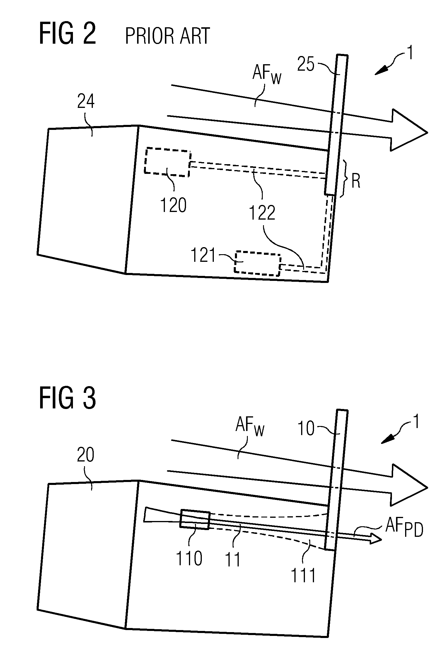
[0035]FIG. 3 shows a schematic representation of the canopy 20 of a wind turbine 2 with a cooling arrangement 1 according to a For simplicity, the heat-generating components and the conduits for a heat transfer fluid are not shown, but may be assumed to be as shown in FIG. 2 above. Here, the cooling capacity of a passive heat exchanger 10 is augmented by an additional cooling means or ventilation means, in this case, an air channel 11 arranged in the interior of the canopy 20, with an air inlet 110 on the side of the canopy 20, and an air outlet 111 arranged to open onto the passive heat exchanger 20. The air channel 11 with its air inlet 110 and air outlet 111 is arranged to make use of the pressure difference in air pressure at different regions about the canopy, so that the air pressure at the air outlet 111 is lower than at the air inlet 110. The air outlet 111 is arranged to open directly onto the heat exchanger 10. In this way, airflow AFPD is effectively drawn of its own acc...

second embodiment

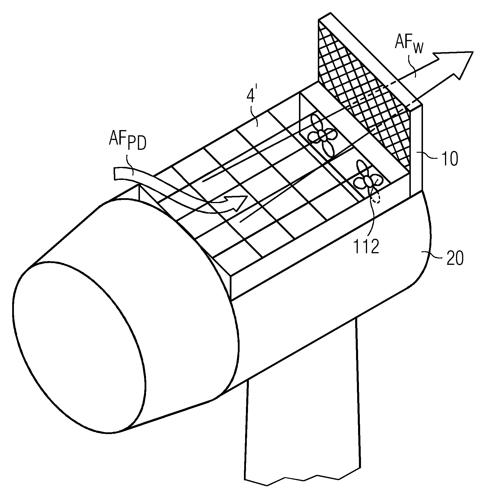
[0036]FIG. 4 shows a schematic representation of the canopy 20 of a wind turbine 2 with a cooling arrangement according to a This diagram also shows the fins 101 of the heat exchanger 10. Here, the passive heat exchanger 10 or panel 10 is mounted on the canopy 20 in such a way that it forms part of a heli-hoist platform 4 on top of the canopy 20. The height of the panel 10 in this embodiment does not exceed 1.5 m above the height of the platform floor, since 1.5 m is the maximum allowable height according to the European aviation authorities. A helicopter may therefore safely hover above the platform while maintenance workers are lowered to or lifted from the platform 4, for example by means of a motorised winch in the helicopter. Any railings 40 or safety features such as warning lights 41 may be arranged to avoid any obstruction of an airflow AFW over the panel 10.

third embodiment

[0037]FIG. 5 shows a schematic representation of a wind turbine 2 with a cooling arrangement 1 according to a Here, the canopy 20, passive heat exchanger 10 and inlets 110 are shown from above. The cross-sectional view of the passive heat exchanger 10 schematically indicates a heat dissipating structure 101 arranged within a housing 100, for example an aluminium housing 100, with a plurality of vertical fins 101 separated by intervening spaces to maximise the area of the heat-dissipating structure 101. In this embodiment, two air channels 11 are arranged within the canopy 20. The diagram also shows a possible shape for the air channels 11, in this case, the air inlets 110 are positioned to either side of a highest part of the canopy 20, and the air outlets 111 are relatively wide, flaring towards the ends of the channels 11 to give a combined opening onto the base of the passive heat exchanger 10. Again, the air outlets 111 are arranged to open directly onto the hottest part of the...


PUM


Abstract

The disclosure describes a wind turbine cooling arrangement including a passive heat exchanger arranged to absorb heat from a cooling circuit of a wind turbine, the passive heat exchanger is arranged on the exterior of the canopy to extend above a canopy of the wind turbine. The wind turbine cooling arrangement includes a ventilation arrangement which includes at least one air channel for channelling air onto a surface of the passive heat exchanger. Further described is a wind turbine including such a wind turbine cooling arrangement.

Description

CROSS REFERENCE TO RELATED APPLICATIONS[0001]This application claims priority of European Patent Office application No. 11173997.5 EP filed Jul. 14, 2011. All of the applications are incorporated by reference herein in their entirety.FIELD OF INVENTION[0002]A wind turbine cooling arrangement and a wind turbine comprising such a cooling arrangement are disclosed.BACKGROUND OF INVENTION[0003]During operation of a wind turbine, heat is generated in various components, for example in the field of an electrical machine, in a converter, etc. This heat must somehow be dissipated in order to prevent overheating and heat-damage of the wind turbine components. Therefore, a wind turbine generally also comprises a cooling circuit. Such a cooling circuit may, for example, comprise heat-exchanging modules located close to the source(s) of heat, and these in turn are connected to an arrangement of pipes or tubes in which a coolant or heat transfer fluid circulates. In this way, heat may effectivel...

Claims


Application Information

Patent Timeline
Patent Type & Authority Applications(United States)
IPC IPC(8): F03D9/00
CPCF03D11/00Y02T50/675Y02E10/722F05B2260/20F03D80/60Y02E10/72
Inventor WANG, ALEX YUNDONG
Owner SIEMENS AG
Why Eureka
Try Eureka