Cordless electrical appliances

Active Publication Date: 2013-01-17
STRIX LTD
View PDF6 Cites 22 Cited by
  • Summary
  • Abstract
  • Description
  • Claims
  • Application Information

AI Technical Summary

Benefits of technology

[0013]A particular advantage of the invention is that the two electrical connections may be connected to a DC supply with one of the functional components being selectively energized depending solely on the voltage difference between the two connections. Thus in one set of preferred embodiments an analog DC voltage is used to selectively operate the two functional components. No digital control commands or other means of telemetry are necessarily required to control when the functional unit becomes operational. There is therefore provided a very straightforward solution to the problem of controlling two functional components from a shared pair of electrical connections. In some embodiments it is preferred that the two electrical connections do not carry any digital signals. However, in other embodiments digital signals may be used to provide additional functionality for components in the cordless appliance beyond the selective energization provided by switching polarities.
[0014]Various circuit arrangements may be used to selectively energize at least one of the functional components in response to a change in the relative polarities of the two electrical connections. For example a switch means could be arranged to select between two separate circuits for the two functional components. However the Applicant has devised a particularly simple and elegant arrangement wherein preferably the first and second functional components are connected electrically in parallel between the two electrical connections provided by the connector and a switch means is provided between the first and second functional components, the switch means being arranged to switch ON or OFF depending on the relative polarities of the two electrical connections. The switch means may be in either branch of the parallel circuit.
[0015]It is therefore preferred that the two functional components are connected to the same two electrical connections provided by the cordless connector with a switch for selectively diverting the current in the parallel circuit, the switch being controlled by reversing the relative polarity applied to the two terminals. This means that there is selectively provided an electrical connection to one of the two functional components simply

Problems solved by technology

Although the electrical connections provided by the connector may supply AC, this may make it less straightforward to

Method used


Image

  • Cordless electrical appliances
  • Cordless electrical appliances
  • Cordless electrical appliances

Examples


Example

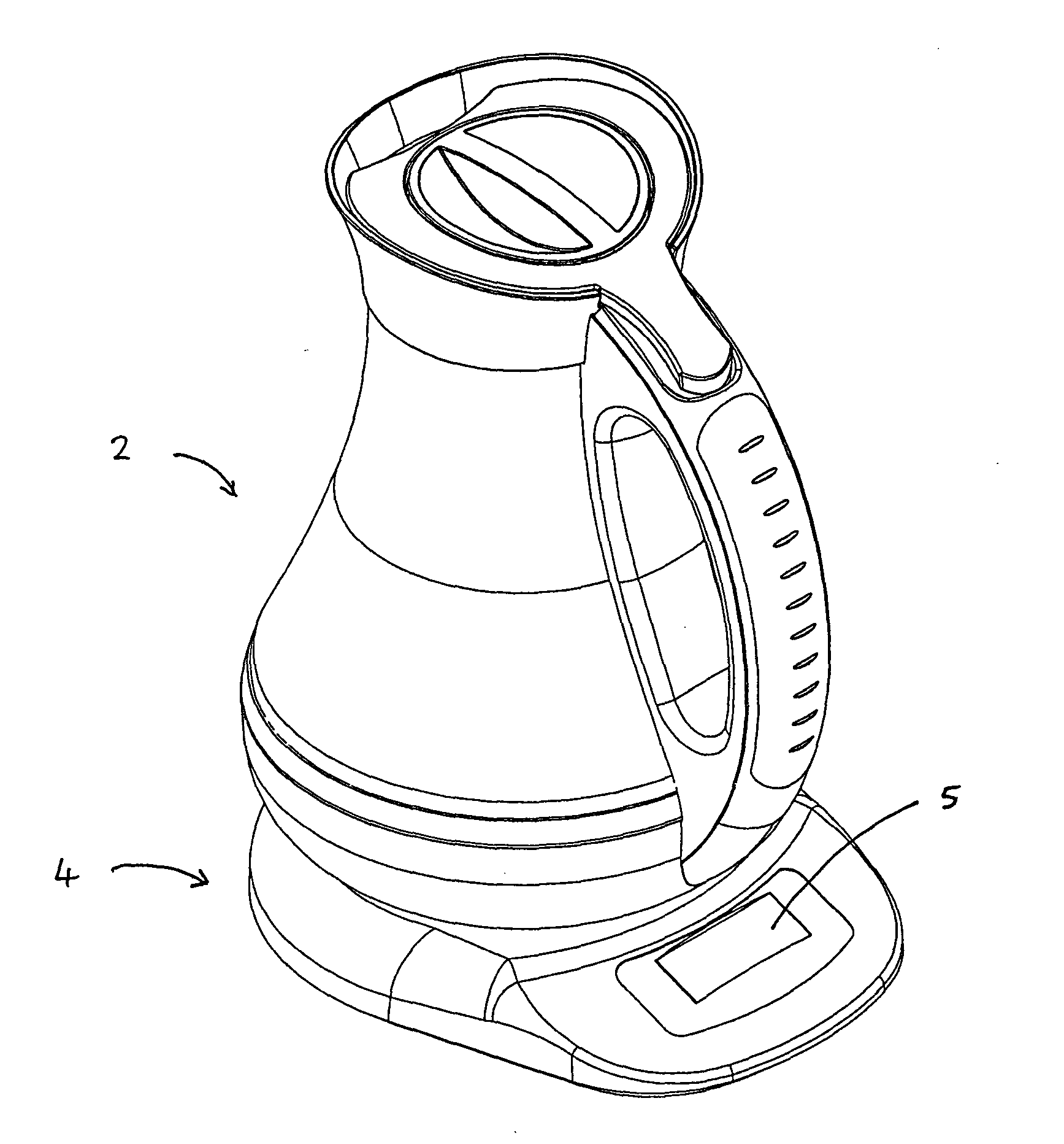
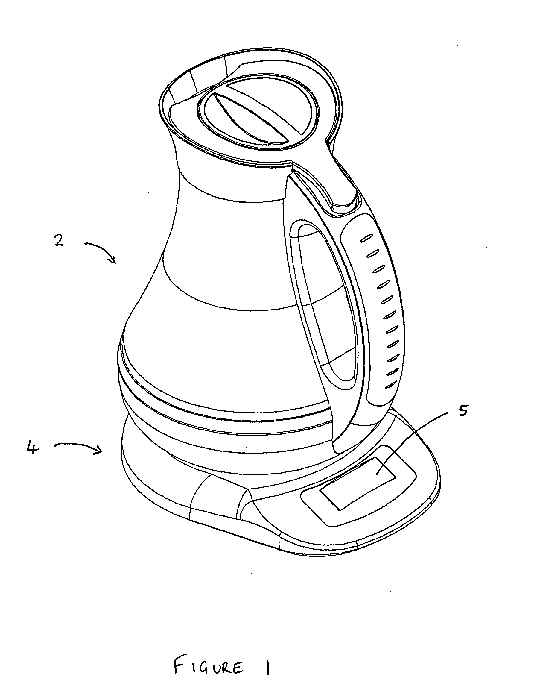
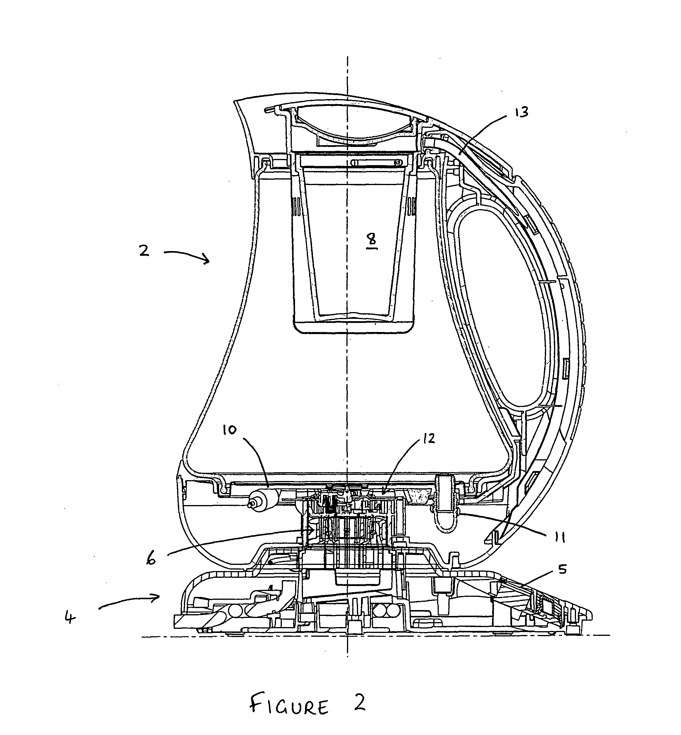
[0063]Turning firstly to FIGS. 1 and 2, there is shown an exemplary liquid heating vessel. The appliance generally comprises a liquid heating vessel part 2 and a base part 4. Electrical connection between the vessel 2 and the base 4 is provided by a 360° cordless connector, designated generally by the numeral 6, which allows the vessel part 2 to be placed on the power base 4 in electrical connection thereto and to operate regardless of its relative angular orientation. The connector 6 may comprise a 5-pole cordless connection system such as the P76 available from Strix Limited. The base 4 includes a power lead (not shown) for connection to the mains power supply and a user interface 5.

[0064]The vessel part 2 is shown as a beverage making jug including an infusion chamber 8 for tea leaves or the like. An opening in the bottom part of the vessel 2 is closed by a heater 10 which may comprise a sheathed heating element or a thick film printed heater mounted to the underside of a heater ...


PUM


Abstract

A cordless electrical appliance comprises an appliance part comprising at least two functional components (T1, M1) and a base for supplying electrical power to the appliance part. A cordless electrical connector (6) makes electrical connection between the appliance part and the base part in use. Both of the functional components (T1, M1) are connected between a pair of electrical connections provided by the connector (6) and arranged such that at least one of the functional components (T1, M1) is selectively energised in response to a change in the relative polarities of the two electrical connections. A switch such as a diode (D1) may be provided between the two functional components (T1, M1), so as to switch ON or OFF the current to a functional component (T1, M1) depending on the polarity of the connections.

Description

[0001]This application is entitled to the benefit of, and incorporates by reference essential subject matter disclosed in PCT Application No. PCT / EP2010 / 006736 filed on Nov. 4, 2010, which claims priority to Great Britain Application No. 0919331.9 filed Nov. 4, 2009 and U.S. Patent Application No. 61 / 257,978 filed Nov. 4, 2009.BACKGROUND OF THE INVENTION[0002]1. Technical Field[0003]The use of a cordless electrical connector in domestic appliances such as kettles, coffee / tea makers and irons for supplying power e.g. to the heating element thereof, and the benefits this brings, are well known. Cordless connectors which allow for engagement of the appliance with the power base regardless of their relative angular orientation, often known as 360° connectors, are popular due to the ease of use which they provide. An example of a basic 3-pole electrical connector is disclosed in the Applicant's prior application published as WO 95 / 08204. Such a connector is available from Strix Limited u...

Claims


Application Information

Patent Timeline
IPC IPC(8): H05K7/00
CPCA47J27/2105
Inventor HOWITT, JAMESHARPER, DAVIDCAMERON, COLIN
Owner STRIX LTD
Why Eureka
Try Eureka