Image forming apparatus that applies necessary amount of lubricant to image bearing member

a technology of lubricant and image bearings, applied in electrographic process apparatus, instruments, optics, etc., can solve the problems of image failure, cleaning failure, and further increase of frictional force, and achieve the effect of suppressing abnormal noise and preventing excessive consumption of lubrican

Inactive Publication Date: 2013-01-17
CANON KK
View PDF6 Cites 36 Cited by
  • Summary
  • Abstract
  • Description
  • Claims
  • Application Information

AI Technical Summary

Benefits of technology

[0014]The present invention provides an image forming apparatus which is configured to apply a necessary amount of a lubricant to an image bearing member while preventing the lubricant from being excessively consumed, and is capable of suppressing abnormal noises from being generated between the image bearing member and a cleaning blade, toner from passing therebetween, and the cleaning blade, the image bearing member, and the like from being deteriorated.
[0016]According to the present invention, it is possible to apply a necessary amount of the lubricant between the cleaning blade and the image bearing member, while preventing the lubricant from being excessively consumed. This makes it possible to provide an image forming apparatus capable of preventing abnormal noises from being generated between the image bearing member and the cleaning blade, toner from passing therebetween, and the cleaning blade, the image bearing member, and the like from being deteriorated.

Problems solved by technology

The cleaning device is configured to be brought into sliding contact with the intermediate transfer belt so as to eliminate powder remaining on the intermediate transfer belt, and hence there arises a problem of a frictional force acting between the cleaning device and the intermediate transfer belt.
Further, when the cleaning device or the intermediate transfer belt deteriorates, the frictional force acting between the both increases to accelerate deterioration of the cleaning device and the intermediate transfer belt, whereby the frictional force further increases.
If the frictional force acting between the cleaning device and the intermediate transfer belt thus increases, abnormal noises may be generated from contact portions of the cleaning device and the intermediate transfer belt where the two are brought into contact with each other, and further, foreign matters may pass between the contact portions, which sometimes causes a cleaning failure.
However, if the lubricant is excessively applied, the excessive amount of the lubricant cannot be scraped by the cleaning device, and as a result, part of the lubricant is conveyed up to a member, such as an electrostatic charger, and soils the member, which sometimes causes an image failure.
That is, the image forming apparatus is required not only to apply a proper amount of the lubricant to the intermediate transfer belt, but also to prevent the lubricant from being excessively consumed, and an image failure from occurring, which is caused by adhesion of the excessive lubricant to the electrostatic charger.
However, when the lubricant is applied in an amount responsive to a change in the traveling speed, it is not configured such that an actual excess or insufficiency of the lubricant is detected, and the lubricant is supplied according to the actual excess or insufficiency of the lubricant.
Therefore, there sometimes occurs a case where an amount of the lubricant required according to the actual state of friction is not properly supplied between the cleaning device and the intermediate transfer belt.

Method used


Image

  • Image forming apparatus that applies necessary amount of lubricant to image bearing member
  • Image forming apparatus that applies necessary amount of lubricant to image bearing member
  • Image forming apparatus that applies necessary amount of lubricant to image bearing member

Examples


first embodiment

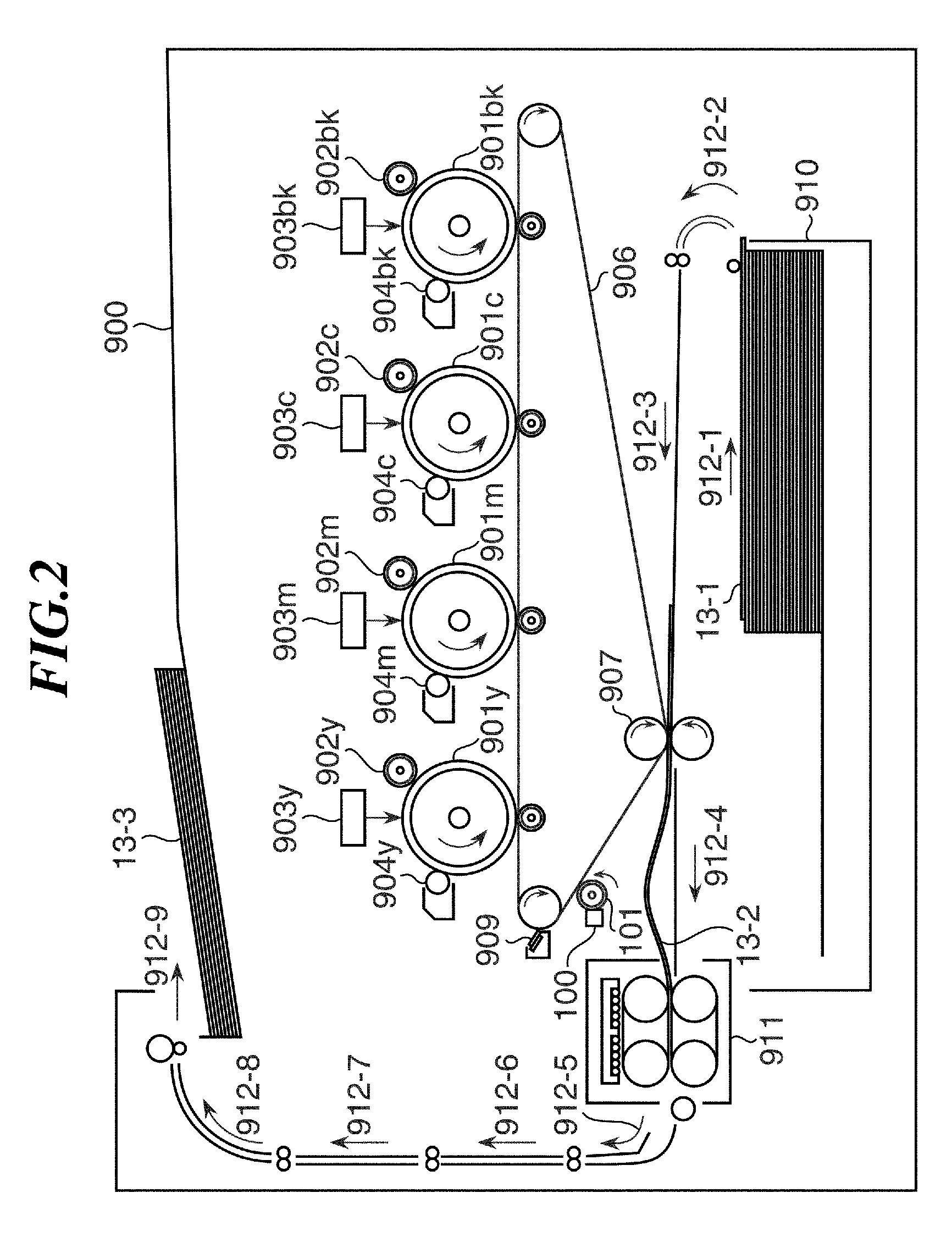
[0030]FIG. 2 is a schematic view of the entire configuration of an electrophotographic color printer as an image forming apparatus according to the present invention, and reference numeral 900 denotes a color printer main unit. The color printer main unit 900 includes developing devices associated with respective four colors of Y (yellow), M (magenta), C (cyan) and K (black), an intermediate transfer belt 906, a sheet feeder 910, secondary transfer rollers 907, and a fixing device 911 arranged therein. In the color printer main unit 900 configured as above, toner images of the respective colors are formed by the developing devices associated with the respective four colors of Y, M, C, and K. The toner images of the respective colors formed as above are sequentially transferred onto the intermediate transfer belt 906 in superimposed relation, and are conveyed to the secondary transfer rollers 907 by a rotating operation of the intermediate transfer belt 906.

[0031]With this operation,...

third embodiment

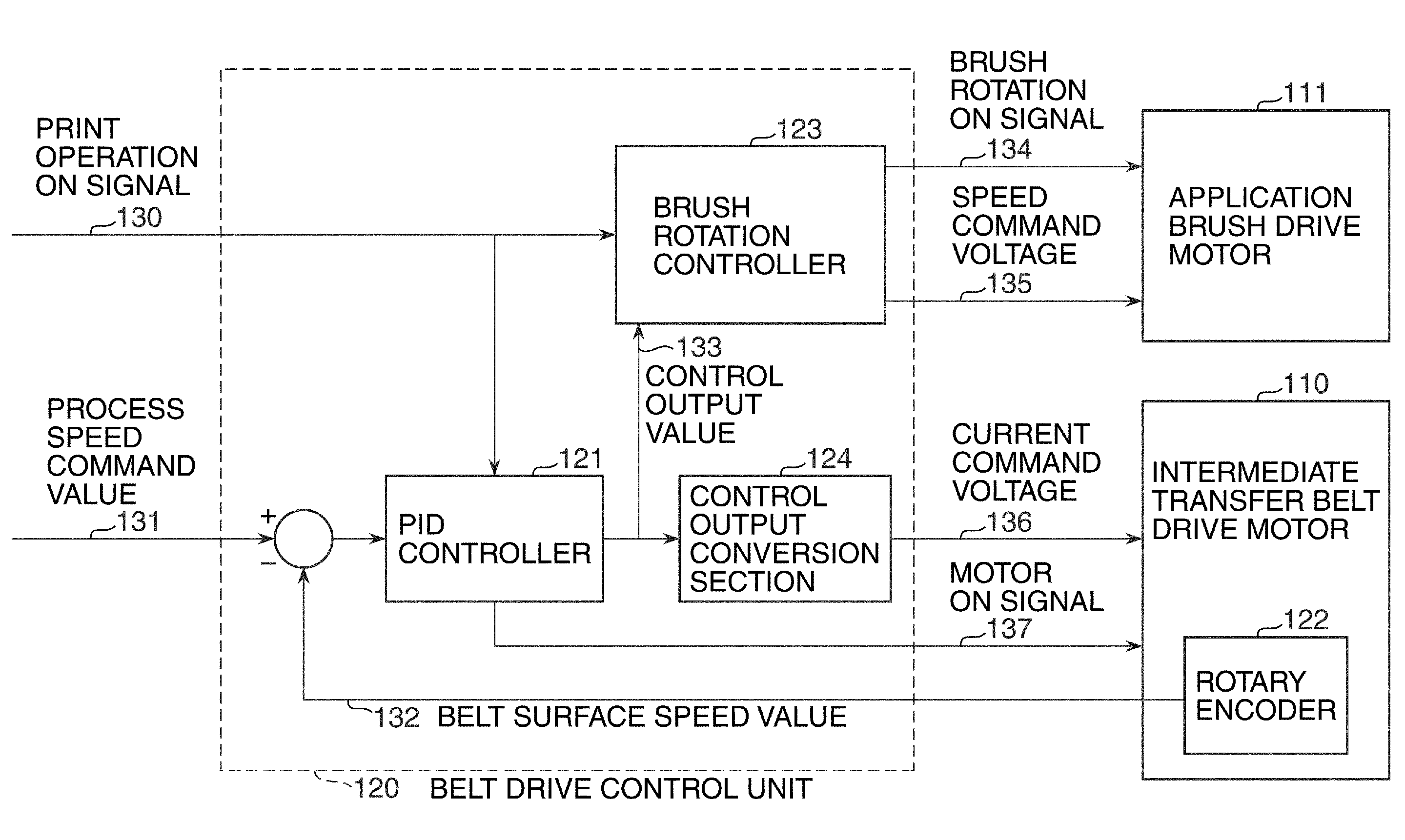
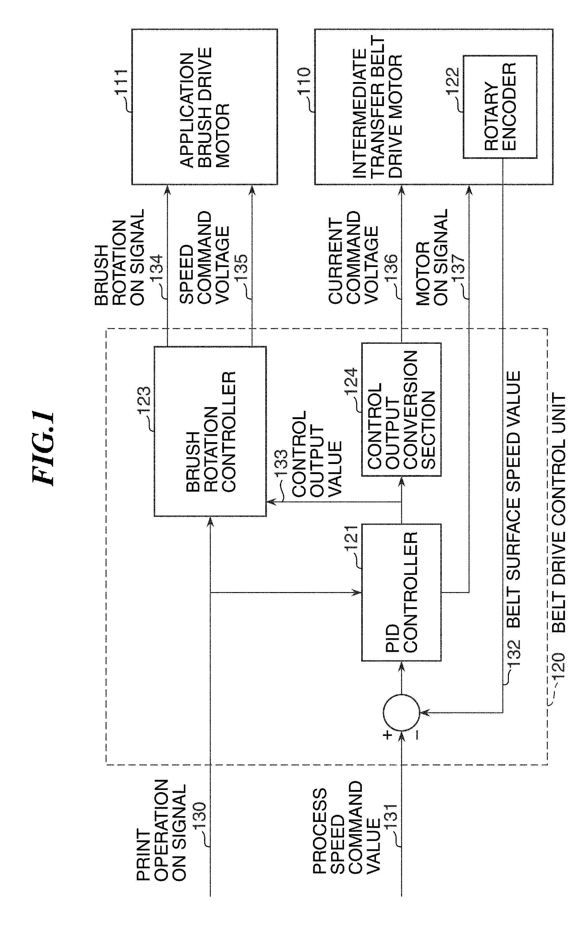
[0096]In the color printer shown in FIG. 9, the PID controller 121 that functions as the first control unit outputs the control output value 133. Then, the control output value 133 is converted to the current command voltage 136 by the control output conversion section 124, and the current command voltage 136 is transmitted to the intermediate transfer belt drive motor 110. The intermediate transfer belt drive motor 110 controlled by the transmitted current command voltage 136 delivers a motor drive current value 138 indicative of a value of a motor drive current caused to flow therethrough 110 by the current command voltage 136, to the brush rotation controller 123.

[0097]Therefore, input to the belt drive control unit 120, is the motor drive current value 138 having a fluctuation in the control output value 133 directly reflected thereon. Therefore, in the third embodiment, the motor drive current fluctuation range P3 is calculated by subtracting the minimum value OutMin of the mo...


PUM


Abstract

An image forming apparatus configured to apply a necessary amount of a lubricant to an image bearing member while preventing the lubricant from being excessively consumed. An intermediate transfer belt drive motor controlled by a PID controller drives an intermediate transfer belt. A brush rotation controller for controlling an application brush drive motor detects fluctuation in a frictional force between a cleaning blade and the intermediate transfer belt, and controls the application brush drive motor such that an amount of lubricant to be applied is an amount corresponding to the detected fluctuation in the frictional force.

Description

BACKGROUND OF THE INVENTION[0001]1. Field of the Invention[0002]The present invention relates to an image forming apparatus equipped with a lubricant application mechanism for applying a lubricant onto an image bearing member, such as a photosensitive drum or an intermediate transfer belt.[0003]2. Description of the Related Art[0004]Conventionally, an electrophotographic image forming apparatus, such as a copying machine or a printer, performs a process for image formation, including forming a toner image on an image bearing member, such as a photosensitive drum and an intermediate transfer belt, transferring the generated toner image on the image bearing member onto a sheet, and then fixing the toner image on the sheet to complete the image formation.[0005]In such an image forming apparatus, not all toner of the toner image formed on the image bearing member, such as the intermediate transfer belt, is transferred onto a sheet, but a slight amount of toner which has not been transfe...

Claims


Application Information

Patent Timeline
Patent Type & Authority Applications(United States)
IPC IPC(8): G03G21/00
CPCG03G21/0094G03G15/5008G03G2215/0129G03G21/0005
Inventor SUDA, TAKEYUKI
Owner CANON KK
Why Eureka
Try Eureka