
Method for optimizing the energy of pumps

a technology of energy optimization and pump, applied in the direction of machines/engines, flexible pump components, positive displacement liquid engines, etc., can solve the problems of difficult to recognise which function is for which pump, and the difficulty of operating these pumps, and achieve the effect of small additional costs

Active Publication Date: 2013-01-17
GRUNDFOS MANAGEMENT AS
View PDF1 Cites 3 Cited by
  • Summary
  • Abstract
  • Description
  • Claims
  • Application Information

AI Technical Summary

Benefits of technology

The invention provides a method that can be carried out using existing equipment in a heating installation, without needing to add any extra measures. The control and data connection can be integrated into the pumps, which is cost-effective. The energy-optimization method can also be applied without needing the data connection.

Problems solved by technology

If a multitude of such pumps cooperate in an installation, be it by way of parallel connection, series connection or a combination thereof, then a complex hydraulic network results, from which is often quite difficult to recognise which function is for which pump.
Of course, it is even more difficult to operate these pumps such that, as a sum, they run even only approximately in an energy-optimized manner.

Method used


Image

  • Method for optimizing the energy of pumps
  • Method for optimizing the energy of pumps
  • Method for optimizing the energy of pumps

Examples


Embodiment Construction

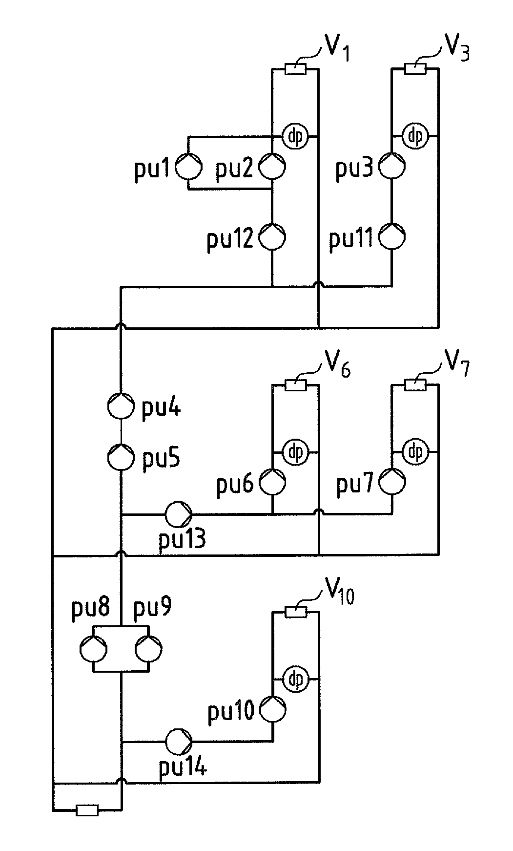
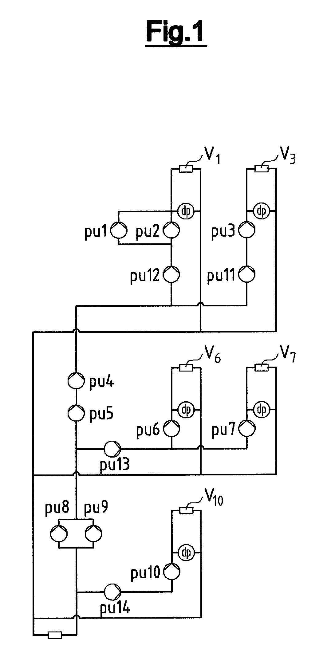
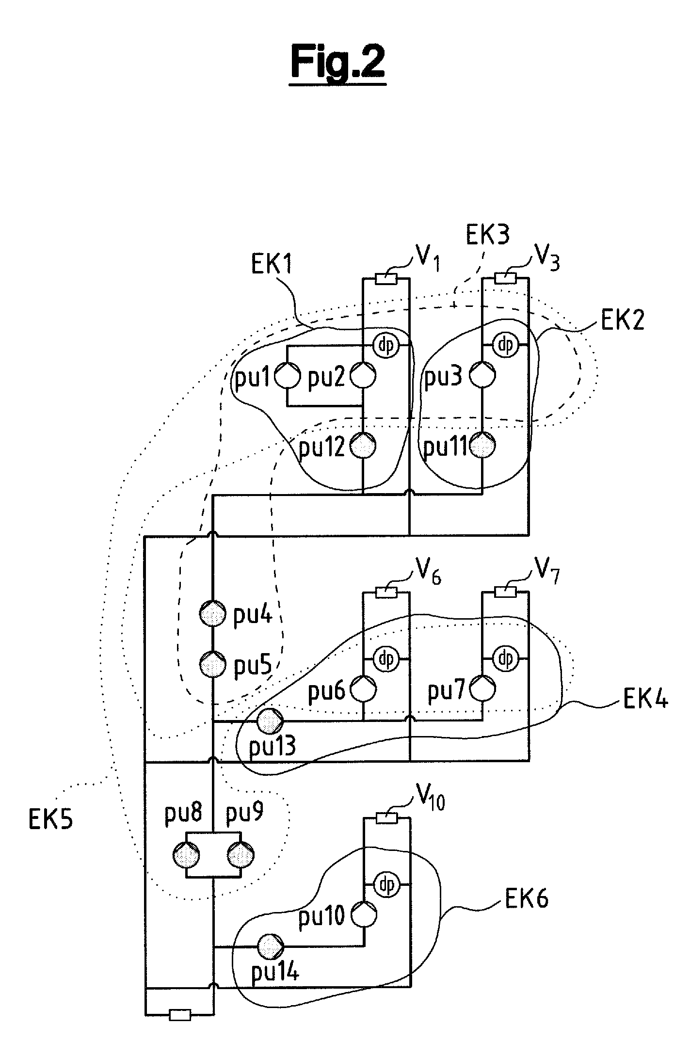
[0079]The hydraulic installation represented by way of FIG. 1 for example represents a heating installation which in total includes 5 consumers or consumer groups V1, V3, V6, V7 and V10, as well as 14 speed-controllable centrifugal pumps pu1-pu14. One should firstly form energy-optimization circuits, in order to optimize the use of the installation with regard to the operation of the pumps. For this, one should firstly ascertain which pumps form pilot pumps, i.e., one should determine the pumps which are directly assigned to a consumer. In the circuit diagram according to FIG. 1, these are the pumps pu1, pu2, pu3, pu6, pu7 and pu10. Thereby, the pumps pu1 and pu2 are connected in parallel and are connected in series upstream of the consumer V1, i.e., assigned in a direct manner. The pumps pu3, pu6, pu7 and pu10 are connected upstream of the respective consumers V3, V6, V7 and V10.

[0080]In order to form energy-optimization circuits, one or more pilot pumps and the subordinate pumps w...


PUM


Abstract

The device for energy-optimization on operation of several centrifugal pumps controlled in rotational speed, in a hydraulic installation, begins firstly with determining which pumps as pilot pumps are assigned directly to a consumer and which pumps are hydraulically connected in series upstream of the pilot pumps. Thereafter, one or more energy-optimization circuits are formed, which in each case consist of one or more pilot pumps and of one or more pumps connected in series upstream, which deliver into the pilot pumps, wherein the energy-optimization circuits are selected such that the pumps connected in series upstream in each case are assigned to only one energy-optimization circuit, whereupon the energy-optimization circuits are energy-optimized with respect to the pumps.

Description

CROSS-REFERENCE TO RELATED APPLICATIONS[0001]This application is a Section 371 of International Application No. PCT / EP2011 / 000184, filed Jan. 18, 2011, which was published in the German language on Jul. 28, 2011, under International Publication No. WO 2011 / 088983 A1 and the disclosure of which is incorporated herein by reference.BACKGROUND OF THE INVENTION[0002]Embodiments of the invention relate to a method for the energy-optimization on operation of several centrifugal pumps controllable with regard to their rotational speed, in a hydraulic installation.[0003]A multitude of pumps, i.e. centrifugal pumps with an electric motor driving this, are particularly installed in heating installations of large buildings or those of a more complex construction type, in order to supply the individual installation parts reliably with fluid or heat. Modern pumps of this type are rotational speed controllable, i.e. they have a frequency converter or rotational speed controller as well as suitable...

Claims


Application Information

Patent Timeline
Patent Type & Authority Applications(United States)
IPC IPC(8): F04B49/06
CPCF04D13/14F04D15/0066F05B2270/101F04D13/0686F05B2270/111F05B2270/309F05B2270/504F05B2270/105F05D2270/02F05D2270/13F05D2270/54F05D2270/309F05D2270/07
Inventor KALLESOE, CARSTEN SKOVMOSEDE PERSIS, CLAUDIO
Owner GRUNDFOS MANAGEMENT AS
Learn More