Dispensing apparatus

a technology of dispensing apparatus and nozzle, which is applied in the direction of biochemistry apparatus and processes, laboratory glassware, instruments, etc., can solve the problems of inability to directly pour liquid discharged from the nozzle onto the area, the cell remains in the area on which the liquid is discharged, and the inability to recover

Active Publication Date: 2013-01-17
PHC HLDG CORP
View PDF7 Cites 19 Cited by
  • Summary
  • Abstract
  • Description
  • Claims
  • Application Information

AI Technical Summary

Problems solved by technology

Therefore, there is such a problem that cells remains in areas on which discharged liquid cannot be poured directly.
There is also another problem that cells such as a lightly attached cell, which is nearly detached by detachment solution such as trypsin, and a cell, which is deposited on and adhered to a bottom surface of a dish, cannot be recovered without directly pouring liquid to the cells for a predetermined period of time with a predetermined flow rate.
Further, since liquid discharged from the nozzle is promptly accumulated in an area in the vicinity of the lowermost part (area illustrated as R2) out of an area of circumference of an inner bottom surface of a dish, it is also impossible to directly pour liquid discharged from a nozzle onto the area.

Method used


Image

  • Dispensing apparatus
  • Dispensing apparatus
  • Dispensing apparatus

Examples


Embodiment Construction

[0027]At least the following details will become apparent from descriptions of this specification and of the accompanying drawings.

Configuration of Dispensing Apparatus

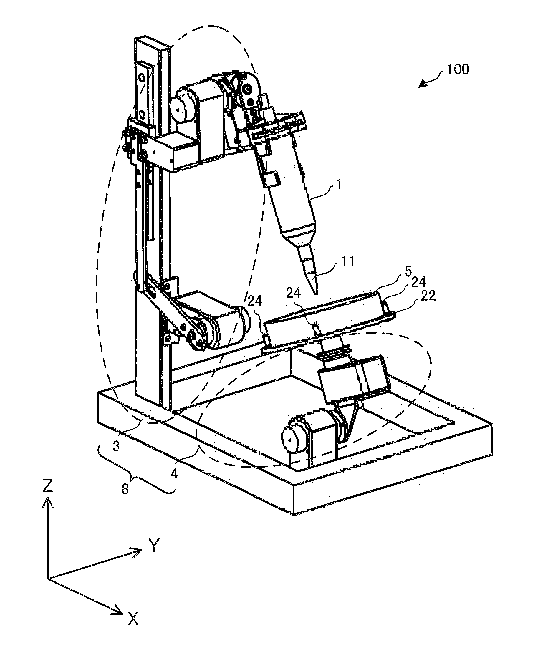
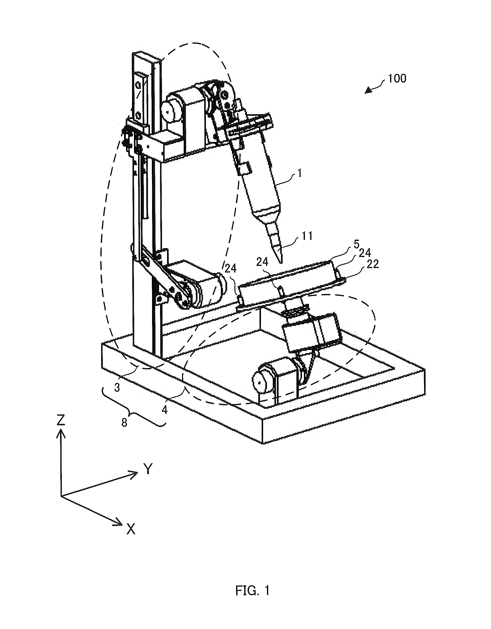
[0028]A configuration of a dispensing apparatus 100 according to an embodiment of the present invention will be described with reference to FIG. 1.

[0029]FIG. 1 depicts a configuration of cell culture equipment as an example of the application of a dispensing apparatus 100 including a dispensing mechanism 101 according to an embodiment of the present invention. The dispensing apparatus (or cell culture equipment) 100 as illustrated in FIG. 1 is configured including: a syringe 1 for dispensing liquid; and a dish mounting portion 22 which is arranged relatively lower than the syringe 1 and is capable of mounting a dish 5 configured to contain liquid to be dispensed, and further including a driving portion 8 configured to move the syringe 1 and the dish mounting portion 22. The driving portion 8 is configured including a...


PUM


Abstract

A dispensing apparatus includes: a dish mounting portion having a mounting surface mounted with a dish having a bottom surface and a side surface surrounding the bottom surface; a syringe, arranged above the dish mounting portion, having a nozzle configured to discharge liquid toward an interior of the dish; and a first driving portion configured to change the syringe in direction with respect to a first axis as a center, wherein the first axis is orthogonal to a normal to the mounting surface of the dish mounting portion.

Description

CROSS-REFERENCE TO RELATED APPLICATION[0001]This application claims the benefit of priority to Japanese Patent Application No. 2011-155925, filed Jul. 14, 2011, of which full contents are incorporated herein by reference.BACKGROUND OF THE INVENTION[0002]1. Field of the Invention[0003]The present invention relates to a dispensing apparatus.[0004]2. Description of the Related Art[0005]A dispensing apparatus configured to discharge liquid from a nozzle using a syringe, etc., has been used for various purposes.[0006]For example, Japanese Patent Application Laid-open Publication No. 2009-291103 discloses an automatic cell culture apparatus including a dispensing apparatus (pipette device) to be used in a pipetting operation applied to a dish (or culture container).[0007]Here, for example, when a cell is cultivated in a dish or a cell is passaged, operations are performed such as an operation of replacing a medium in a dish with a new medium, an operation of recovering a medium from a dis...

Claims


Application Information

Patent Timeline
Patent Type & Authority Applications(United States)
IPC IPC(8): B01L3/02
CPCC12M23/10C12M23/48C12M29/00C12M33/04B01L2400/0487B01L3/021B01L9/52B01L9/54B01L2200/025C12M41/48G01N35/1011
Inventor TOKUMARU, TOMOYOSHI
Owner PHC HLDG CORP
Why Eureka
Try Eureka