Dental implantation system and method

a technology of implanted teeth and implantation systems, applied in the field of dental implanted systems and methods, can solve the problems of inconvenient use, inconvenient use, and limited image provided by systems that rely on optical (viewable) images, and achieve the inability to accurately determine the location of anatomical structures and instruments by computer assisted imaging systems

Active Publication Date: 2013-01-17
PRECISION THROUGH IMAGING
View PDF11 Cites 69 Cited by
  • Summary
  • Abstract
  • Description
  • Claims
  • Application Information

AI Technical Summary

Benefits of technology

[0008]In another aspect, a computer system is provided, comprising an image processor that receives an image of a patient's dentition, and a location system that receives data from a sensor system on a dental handpiece that includes a handpiece drill. The sensor system engages a known surface of a workpiece guide fixed to a dental arch of a patient, and the location system determines based at least in part on the data from the sensor system a location and angular orientation of the handpiece drill in relation to the patient's dentition. The computer system also includes a viewer that generates a display image at a computer display such that the generated display image comprises the image of the patient's dentition and a depiction of the location and angular orientation of the handpiece drill relative to the patient's dentition as determined by the location system. The location system receives updated sensor data and determines based at least in part on the updated sensor data an updated location and angular orientation of the handpiece drill in relation to the patient's dentition, and the viewer adjusts the generated display image to show the updated location and angular orientation of the handpiece drill relative to the patient's dentition. In this way, real time feedback may be provided to the use

Problems solved by technology

Conventional systems that provide such imaging can be cumbersome, complicated, and difficult to use.
Moreover, the images provided by systems that rely on optical (viewable) images can be limited by images that are obscured by fluids, including blood and water found at the implant

Method used


Image

  • Dental implantation system and method
  • Dental implantation system and method
  • Dental implantation system and method

Examples


Embodiment Construction

Definitions

[0045]Unless expressly defined, the terms used herein have meanings as customarily used in the dental and medical arts.

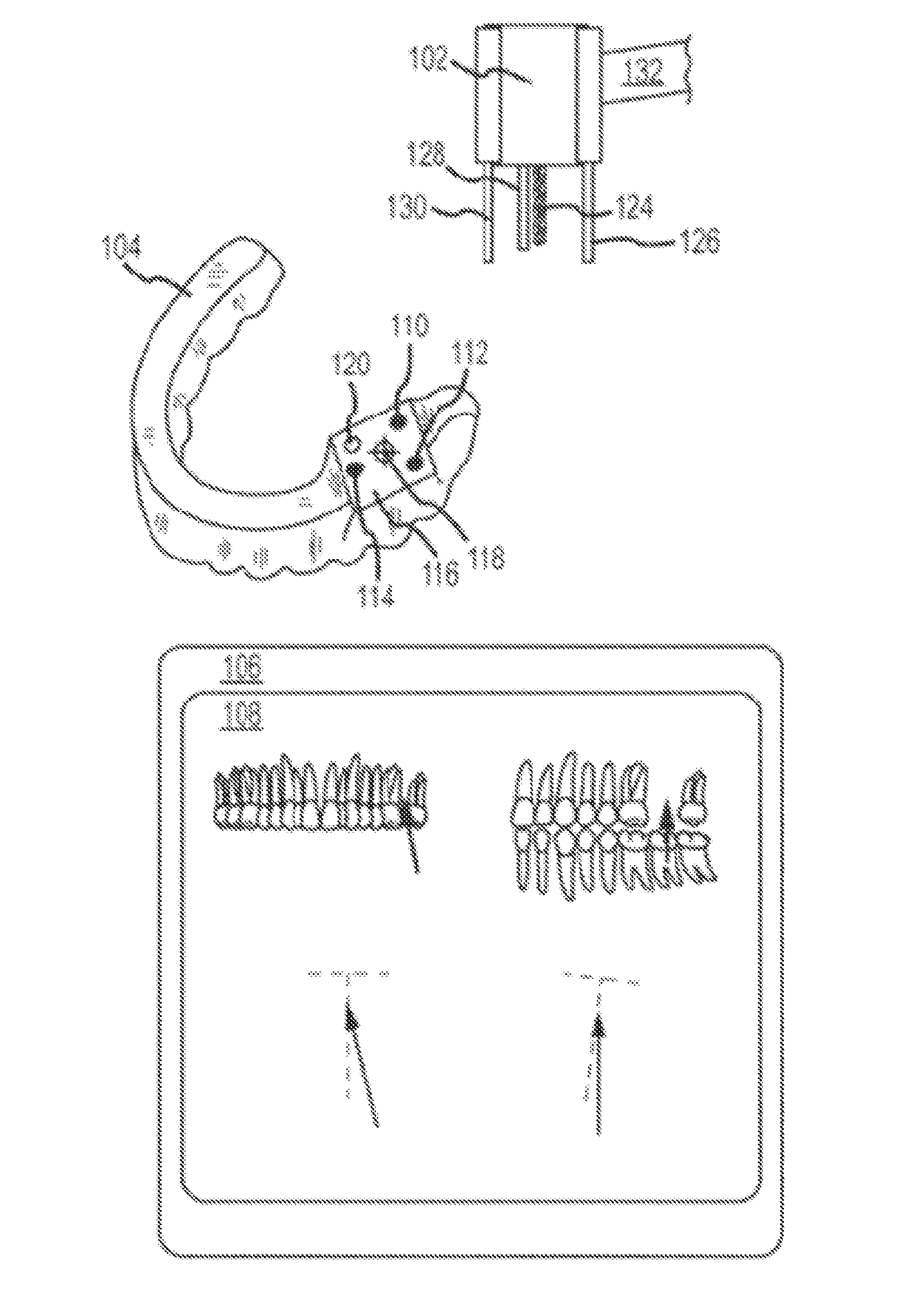
[0046]The terms “implant,”“dental implant” and the like (noun), refer in the customary sense to a permanently placed (i.e., non-removable) prosthetic device which includes an artificial tooth root replacement. In some embodiments, the implant includes an implant fixture which is embedded in bone and undergoes integration (i.e., osseointegration) to form a stable integrated structure capable of supporting an artificial tooth or providing support for another dental structure including, for example but not limited to, an implant-support bridge or implant-supported denture, as known in the art. The implant fixture is joined to an implant abutment, typically near the gingival surface, to which implant abutment can be affixed a replacement tooth (i.e., pontic). The term “implant” (verb) refers in the customary sense to the placement of a dental implant. “Implan...


PUM

PropertyMeasurementUnit
Depthaaaaaaaaaa
Distanceaaaaaaaaaa

Abstract

Drilling of an implant shaft is carried out with a handpiece tool whose location and angular orientation with respect to a radiographic working guide is updated in real time with respect to the radiographic working guide and anatomical structures of the patient, free of viewing obstructions. Prior to the drilling, the radiographic working guide is fitted to a particular patient. Real-time imaging support is provided on a display of a computer, wherein the radiographic workpiece guide includes a plurality of fiducial markers that define a substantially planar reference surface of the radiographic workpiece guide. The radiographic workpiece guide also includes an alignment structure located a predetermined distance from a pilot hole proximate the work site. The image is updated based on an initial radiographic scan and updated position information from the handpiece tool as to location and angular orientation of the handpiece tool relative to the workpiece guide.

Description

CROSS-REFERENCES TO RELATED APPLICATIONS[0001]This application is a continuation of PCT / US2011 / 022290, filed Jan. 24, 2011, which in turn claims priority from provisional U.S. patent application Ser. No. 61 / 297,389, titled “Dental Implantation System and Method” and filed Jan. 22, 2010, the entire disclosures of which are hereby incorporated herein and for all purposes.BACKGROUND OF THE INVENTION[0002]Dental implant surgery involves placing a prosthetic device such as one or more artificial replacement teeth in the mouth of a patient. Such prosthetic devices must be precisely placed in the mouth for the best aesthetic and functional results. Precise placement of the prosthetic device requires suitable preparation of the implant site with respect to surrounding tissue and bone. The prosthetic device typically comprises a tooth implant abutment, a pontic attached thereto, and a tooth implant fixture that extends from the abutment and is received into an implant shaft drilled into the ...

Claims


Application Information

Patent Timeline
IPC IPC(8): A61C8/00A61B6/14A61C19/04A61C3/02A61B1/24A61C5/77
CPCA61B19/201A61B2017/3407A61B2019/204A61B2019/462Y10T29/49567A61B2019/5287A61B2019/5466A61C1/084A61C8/0089A61B2019/5259A61B90/16A61B2090/363A61B90/11A61B2090/062A61B2034/2059A61B90/39A61B2090/3966A61C17/08A61B6/14
Inventor MOFFSON, ALLEN M.AZMOON, MAJID
Owner PRECISION THROUGH IMAGING
Why Eureka
Try Eureka