
Connector

a technology of connecting rods and connectors, applied in the direction of coupling device details, coupling device connections, securing/insulating coupling contact members, etc., can solve the problems waterproof performance, and achieve the effect of reducing fluidproof performance, waterproof performance not reduced, and small vertical dimension

Inactive Publication Date: 2013-01-17
SUMITOMO WIRING SYST LTD
View PDF30 Cites 14 Cited by
  • Summary
  • Abstract
  • Description
  • Claims
  • Application Information

AI Technical Summary

Benefits of technology

The patent text describes a design for a terminal fitting that reduces stress on the seal, even when there is force applied to the connecting portion. This is achieved through the use of a resilient portion that can deform without affecting the seal, as well as a retaining portion that increases the connection force with the housing. The design also reduces rotational force and retains a strong seal. These technical features make the terminal fitting more robust and reliable in high-performance applications.

Problems solved by technology

As a result, a force acting on the connecting portion will not produce a stress in the seal that could reduce fluidproof performance.
As a result, a vertical force on the connecting portion will not produce a stress in the seal and waterproof performance is not reduced.

Method used


Image

  • Connector
  • Connector
  • Connector

Examples


Embodiment Construction

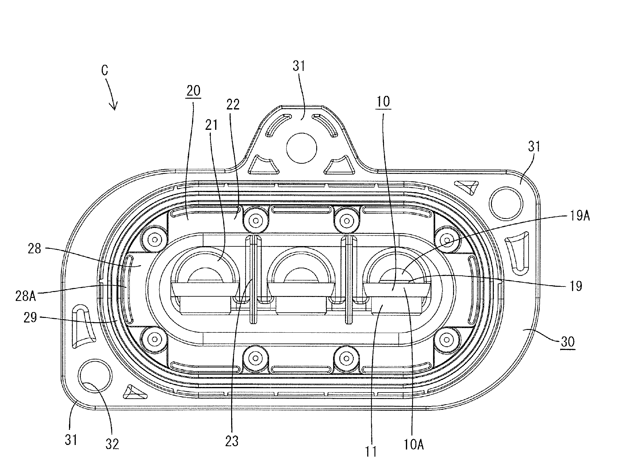
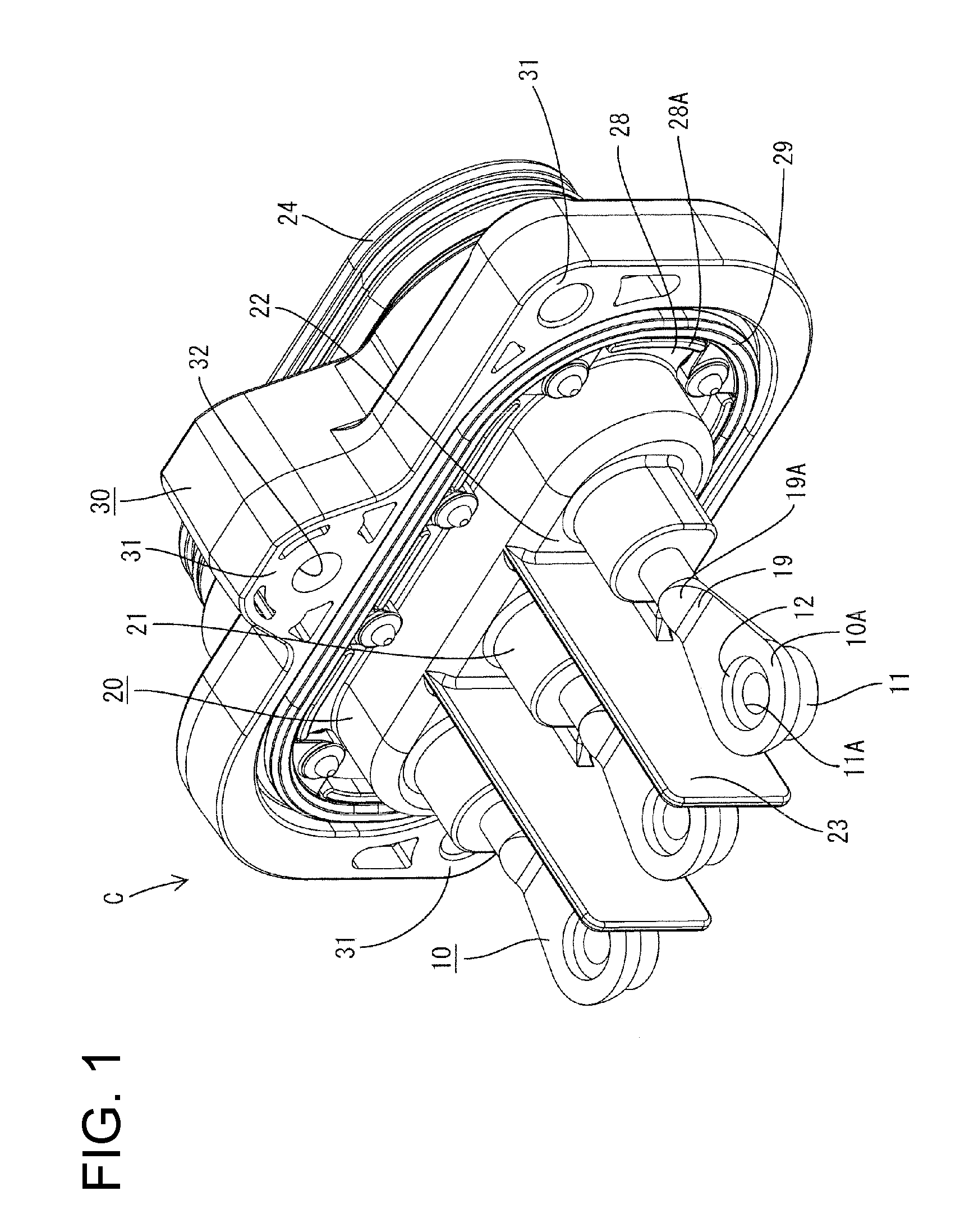
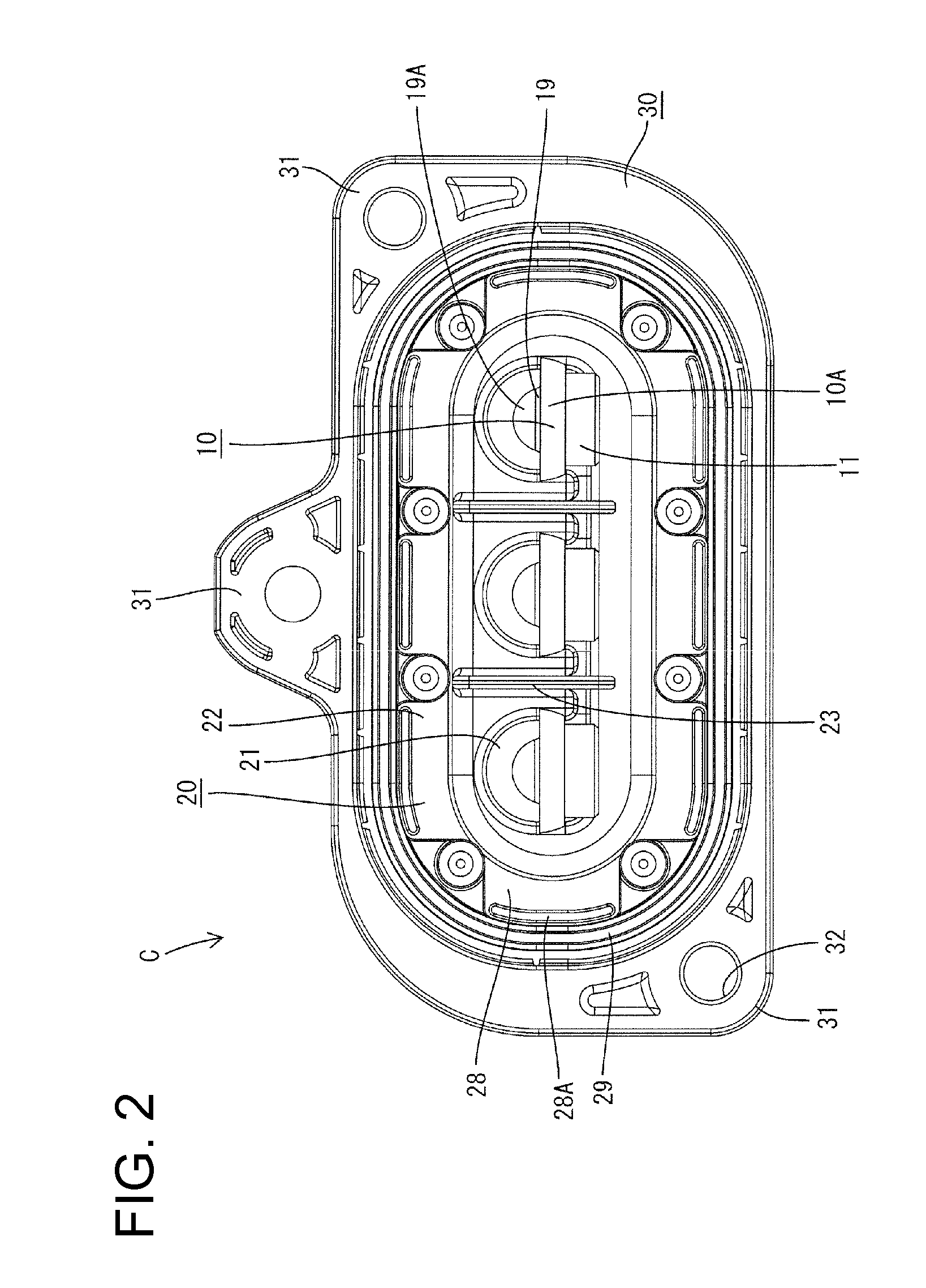
[0028]A connector C in this embodiment is a device connector used to supply power to an unillustrated load or device (e.g. motor mounted in an electric vehicle, a hybrid vehicle or the like). In the following description, an end (front of FIG. 1) to be connected with the device is referred to as the front, an opposite end is referred to as the rear, and upper and lower sides of FIG. 1 are referred to as the top and bottom for respective constituent members. Note that the device is to be housed in an unillustrated conductive metal case having a shield function and the connector C is to be mounted in a mounting hole in the case.

[0029]The connector C has terminal fittings 10 with embedded portions embedded in a housing 20 by insert molding so that a unitary matrix of synthetic resin surrounds and engages parts of the terminal fittings 10.

[0030]As shown in FIG. 1, the housing 20 has substantially cylindrical terminal holding portions 21 and substantially central portions of the terminal...


PUM


Abstract

A connector (C) is formed by insert molding such that terminal fittings (10) are embedded in a housing (20). A connecting portion (10A) provided at the front end of the terminal fitting (10) for connection to a mating terminal fitting projects forward from the housing (20) and a part of the terminal fitting (10) located behind the connecting portion (10A) is embedded in the housing (20). A seal (15) is provided in close contact with an embedded portion (10C) of the terminal fitting (10) embedded in the housing (20) and a resilient portion (19) is provided at a position before the seal (15) and outside the housing (20).

Description

BACKGROUND OF THE INVENTION[0001]1. Field of the Invention[0002]The invention relates to a connector.[0003]2. Description of the Related Art[0004]Known connectors are formed by insert molding so that part of a terminal fitting is embedded in a housing. More particularly, a connecting portion is provided at the front end of the terminal fitting and projects forward from the housing for connection to a mating terminal fitting and a part behind the connecting portion is embedded in the housing. A clearance may be formed in an adhering part of the terminal fitting and the housing of the insert molded connector due to low adhesion between two materials. Accordingly, water or oil may intrude into the housing through that clearance.[0005]U.S. Pat. No. 7,070,449 discloses adhering a seal to the outer peripheral surface of a part of a terminal fitting to be embedded in a housing and then performing insert-molding to ensure good waterproofing. However, waterproof performance may be reduced by...

Claims


Application Information

Patent Timeline
Patent Type & Authority Applications(United States)
IPC IPC(8): H01R13/40
CPCH01R43/24H01R13/521
Inventor MAEGAWA, AKIHITO
Owner SUMITOMO WIRING SYST LTD
Learn More