
Stand Alone Energy-Based Tissue Clips

a tissue clip and energy-based technology, applied in the field of use, can solve the problems of occupying the instrument etc., and occupying the surgeon's hand and waiting for the instrument to be compressed and heated

Active Publication Date: 2013-01-17
TYCO HEALTHCARE GRP LP
View PDF16 Cites 99 Cited by
  • Summary
  • Abstract
  • Description
  • Claims
  • Application Information

AI Technical Summary

Benefits of technology

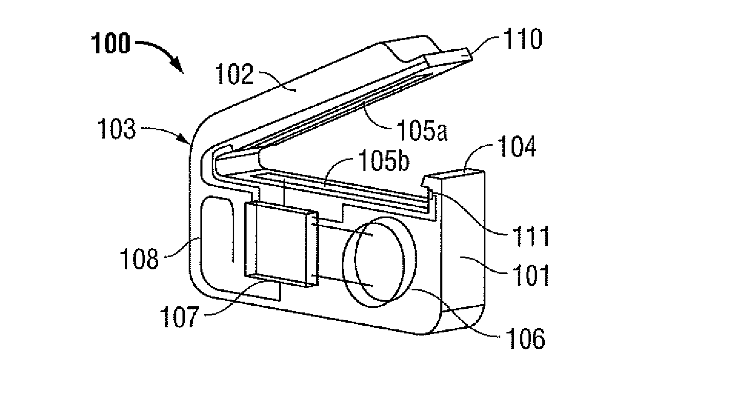
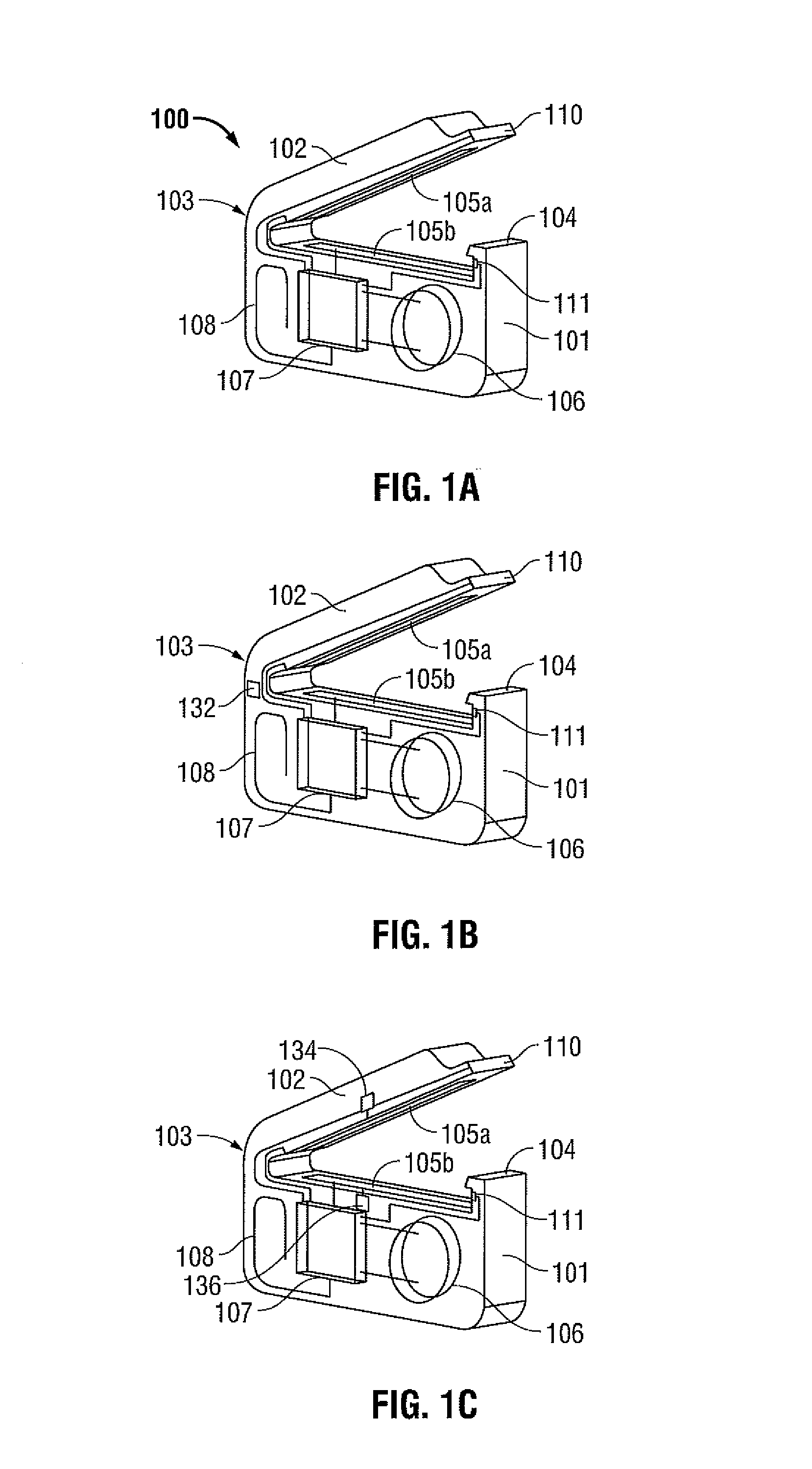
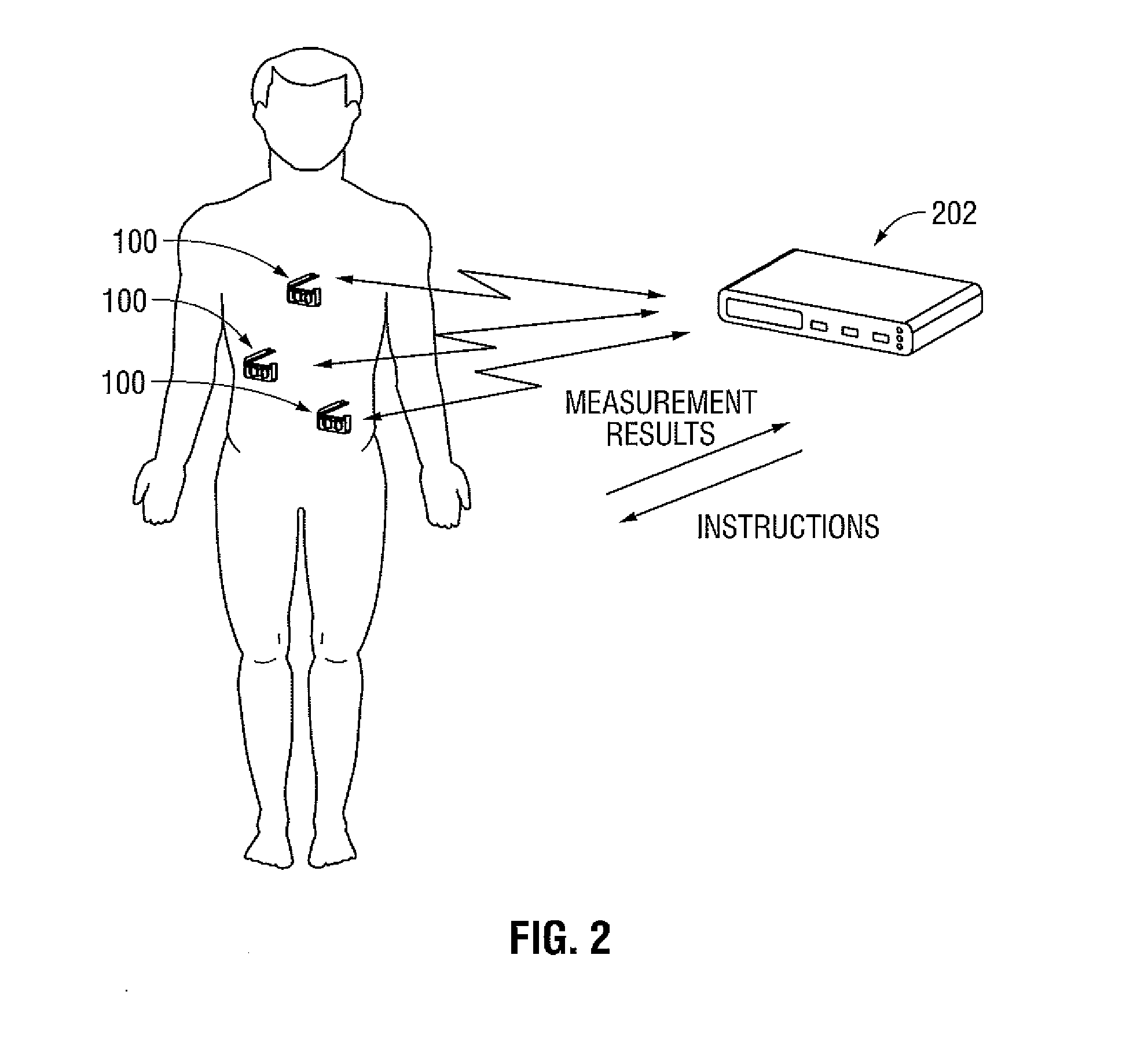
The present disclosure provides a tissue clip with an electrode assembly that can seal tissue. The clip has a first arm and a second arm moveable relative to the first arm to approximate tissue and a body with a power source and a control unit. The electrode assembly includes a first electrode and a retaining clip to grasp tissue between the first and second electrodes. The clip can also have a sensor to determine tissue parameters. The electrodes can be made of stainless steel or a copper alloy, or a piezo electric sensor. The clip can also have a cutting mechanism to cut tissue after sealing it. The technical effects of the invention include improved sealing of tissue with reduced energy usage and a simplified design for easy use.

Problems solved by technology

One drawback of using staples is that staples generally remain inside the body.
This approach has several disadvantages which are inherent to most energy-based sealing instruments.
Compressing and heating of tissue takes considerable time in which the surgeon has to hold the instrument and wait.
This may interfere with the continuous flow of a surgical procedure.
In order to reduce sealing time, power has to be increased that may result in higher risk of thermal damage and to more bulky instrument and generator designs.
Additionally, after several cycles of successive sealing, the jaw members of the electrosurgical instrument may become overheated and a surgeon may need to wait until they cool to avoid poor quality sealing and thermal damage of adjacent tissues.

Method used


Image

  • Stand Alone Energy-Based Tissue Clips
  • Stand Alone Energy-Based Tissue Clips
  • Stand Alone Energy-Based Tissue Clips

Examples


Embodiment Construction

[0058]Particular embodiments of the present disclosure are described hereinbelow with reference to the accompanying drawings; however, the disclosed embodiments are merely examples of the disclosure and may be embodied in various forms. Well-known functions or constructions are not described in detail to avoid obscuring the present disclosure in unnecessary detail. Therefore, specific structural and functional details disclosed herein are not to be interpreted as limiting, but merely as a basis for the claims and as a representative basis for teaching one skilled in the art to variously employ the present disclosure in virtually any appropriately detailed structure.

[0059]Like reference numerals may refer to similar or identical elements throughout the description of the figures. As shown in the drawings and described throughout the following description, as is traditional when referring to relative positioning on a surgical instrument, the term “proximal” refers to the end of the ap...


PUM


Abstract

The present disclosure is directed to a tissue clip for use in electrosurgical procedures. The tissue clip includes an arm having a first electrode formed thereon. The tissue clip also includes a body pivotally coupled to the arm. The body includes a power source and a second electrode. The arm is moveable from a first position relative to the body for approximating tissue and a second position closer to the body for grasping tissue therebetween

Description

BACKGROUND[0001]1. Technical Field[0002]The present disclosure relates to the use of energy-based electrosurgical instruments. More particularly, the present disclosure is directed to the use of stand alone energy-based tissue clips to provide energy to seal, cauterize, ablate or destroy cells and / or tissue.[0003]2. Background of the Related Art[0004]Surgical staplers are widely used to join or bond tissues together and to provide hemostasis of adjacent tissues. These staples can be employed in combination with electrosurgical stapling apparatus where thermogenic energy is utilized to provide short-term hemostasis and sealing. One drawback of using staples is that staples generally remain inside the body.[0005]Another method of joining or bonding tissue is based on radio frequency (RF) energy applied to tissue. Existing RF energy-based tissue sealing instruments utilize metal electrodes combined with jaws which grasp and hold sealed tissue. Energy-based tissue sealing involves compr...

Claims


Application Information

Patent Timeline
IPC IPC(8): A61B18/14A61B18/20
CPCA61B17/122A61B2018/0063A61B18/1442A61B18/20A61B2017/00004A61B2017/00026A61B2017/00119A61B2017/00199A61B2017/00221A61B2017/00517A61B2017/00734A61B2017/00867A61B2018/00273A61B2018/00428A61B2018/00607A61B2018/00642A61B2018/00702A61B2018/00779A61B2018/00875A61B2018/1226A61B2019/465A61B5/05A61B2090/065
Inventor CHERNOV, BORISMISUCHENKO, IGORISMARTSINOVSKIY, GEORGYVERBITSKY, MIKHAIL
Owner TYCO HEALTHCARE GRP LP
Learn More