
Real-time peak utility usage charge assessment methods

a utility and peak charge technology, applied in the field of peak mitigation and load leveling charge assessment service methods, can solve the problems of large fees, complex electronic equipment, and difficulty in controlling the amount that appears on the bill, and achieve the effect of increasing awareness

Inactive Publication Date: 2013-01-17
GREEN CHARGE NETWORKS
View PDF7 Cites 33 Cited by
  • Summary
  • Abstract
  • Description
  • Claims
  • Application Information

AI Technical Summary

Benefits of technology

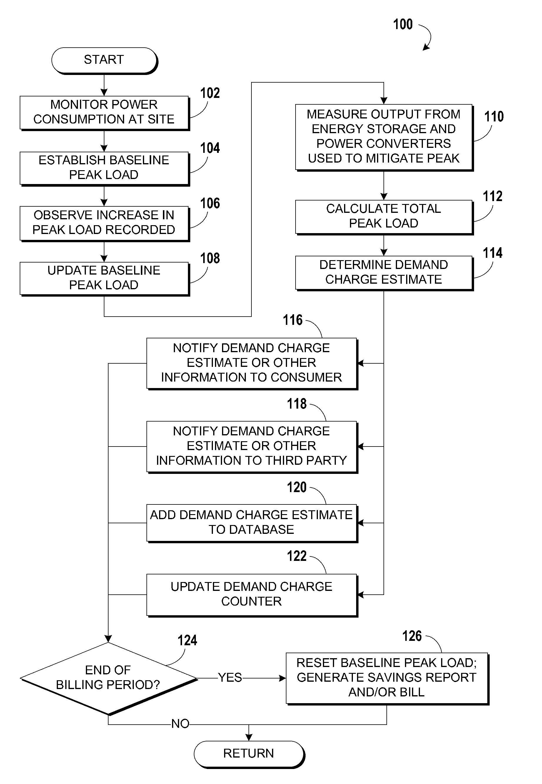
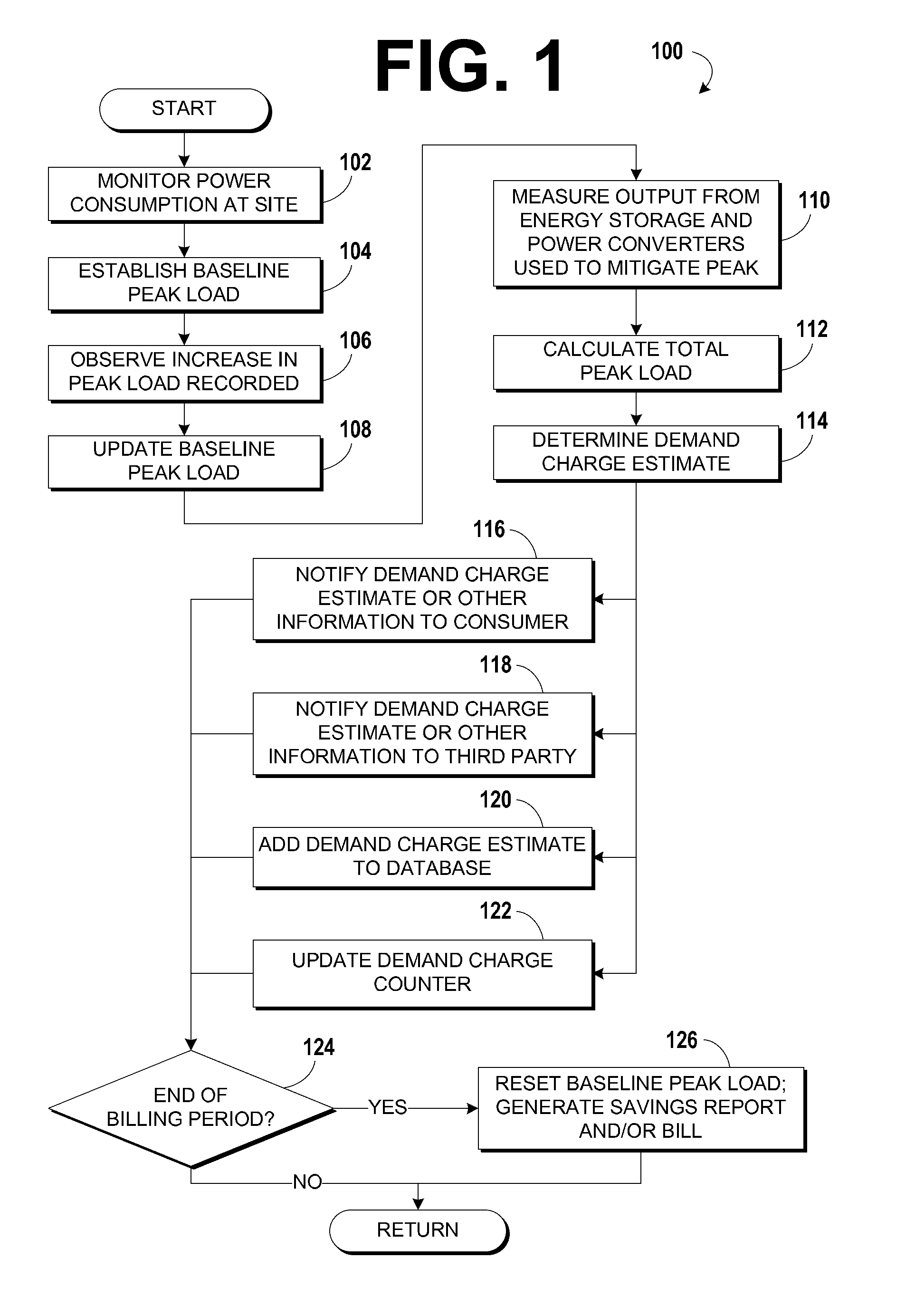
The patent describes a system that monitors changes in electrical demand in a facility or site, and updates a projection of the demand charge based on these changes. This helps to mitigate peak loads and provides more accurate information to the customer about their demand.

Problems solved by technology

These charges can result in substantial fees in some cases.
Despite the magnitude of demand charges, they are frequently a poorly-understood portion of customers' electricity bills, partially because the source of demand charges is not usually clearly conveyed and explained to the customer.
Even customers that have an understanding of the origin of demand charges may have difficulty in controlling the amount that appears on their bill due to what may be unpredictable electrical usage patterns.
While a decrease in demand charges in a bill may be readily noticed by these customers after the billing period ends, real-time information about the demand charge and how it will be billed is not accessible for the customer to monitor, to track, and to keep in awareness, so demand charges may still be higher than they could be with careful monitoring and planning.
However, demand charge management systems may comprise sophisticated and expensive electronic equipment, and it may therefore be burdensome for customers to afford to use and maintain the batteries, power converters, computers, and other components found in them.

Method used


Image

  • Real-time peak utility usage charge assessment methods
  • Real-time peak utility usage charge assessment methods
  • Real-time peak utility usage charge assessment methods

Examples


Embodiment Construction

[0020]The detailed description set forth below in connection with the appended drawings is intended as a description of the presently preferred embodiments of systems and methods provided in accordance with aspects of the present invention and is not intended to represent the only forms in which the present invention may be constructed or utilized. The description sets forth the features and steps for making and using the test systems and methods of the present invention in connection with the illustrated embodiments. It is to be understood, however, that the same or equivalent functions and structures may be accomplished by different embodiments that are also intended to be encompassed within the spirit and scope of the invention.

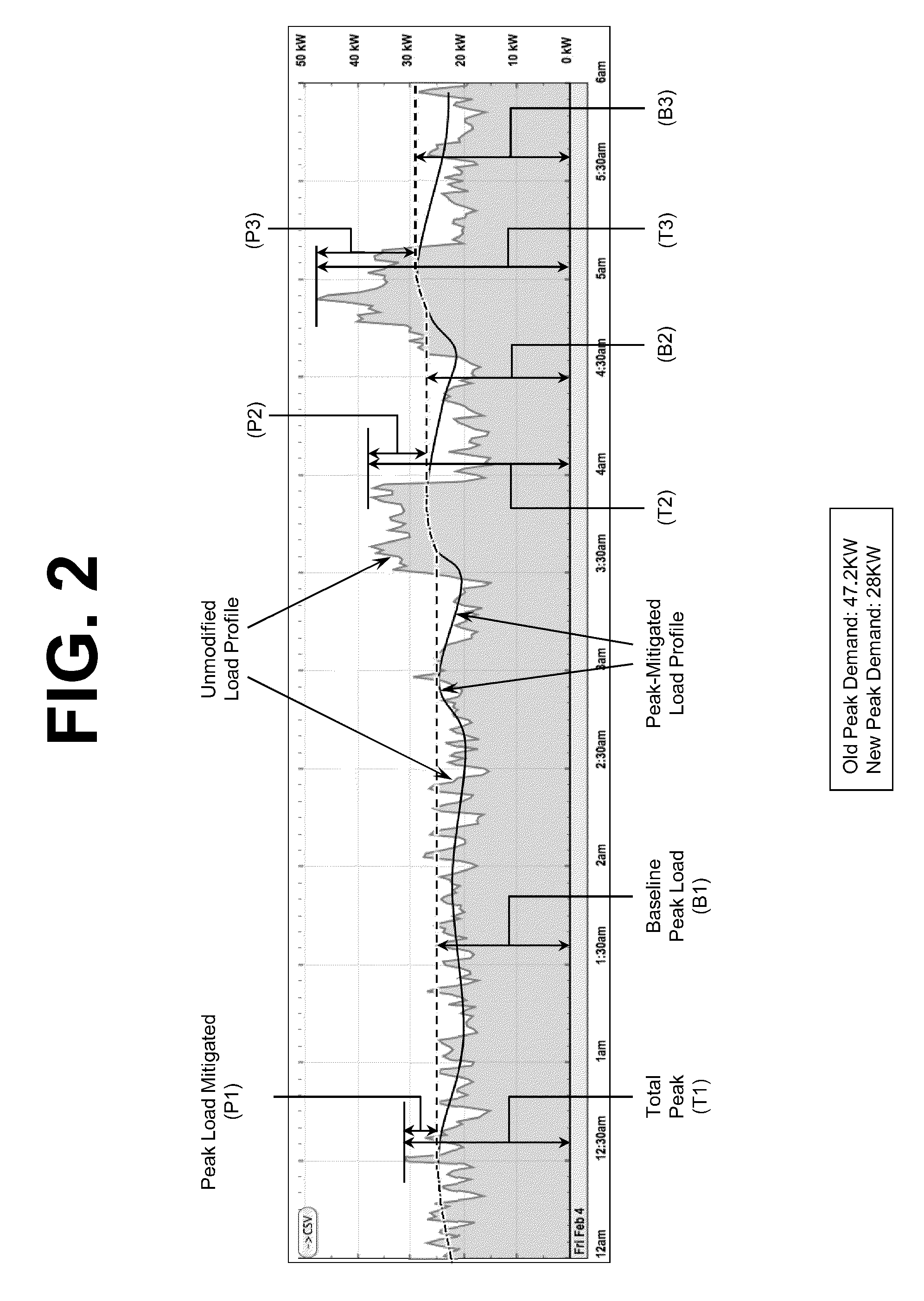
[0021]Peak mitigation is a process by which demand charges may be diminished by shaving the magnitude of short peaks or spikes in a location's electrical utility consumption. A peak mitigation apparatus may be used by discharging energy storage into the lo...


PUM


Abstract

Some embodiments are systems which calculate the amount of electric power that a peak mitigation system provides in real time and translate that information into a real-time estimate of a peak utility usage charge that appears on the utility bill of the customer. These systems may facilitate a determination of the monetary value of demand charges saved by peak mitigation and load leveling and a notification to a customer of the savings realized. Some systems described herein provide a method of billing a customer based on the electricity usage savings accumulated through demand charge reduction procedures. One embodiment monitors the mitigation of peak loads as they occur, detects and measures incremental changes in demand charge-producing peaks and updates a projection when incremental demand charge changes occur. The demand charge projection may be presented to the customer, aggregated with demand charge projections of other sites, and displayed to increase awareness.

Description

CROSS REFERENCE TO RELATED APPLICATIONS[0001]Priority is claimed to the following related pending U.S. Provisional Patent Application, which is hereby incorporated by reference in its entirety: Ser. No. 61 / 508,525, filed Jul. 15, 2011.BACKGROUND[0002]The present invention relates to the fields of peak mitigation, load leveling charge assessment service methods, and related fields.[0003]Commercial electric customers are commonly assessed a monthly fee called a “demand charge” that is determined by the highest power throughput recorded by a utility's billing meter during a billing cycle. These charges can result in substantial fees in some cases. For example, a customer with 50 kW of peak load during the billing period in certain parts of the United States could be assessed as much as $1,000 (or $20 per kW) per billing cycle. Despite the magnitude of demand charges, they are frequently a poorly-understood portion of customers' electricity bills, partially because the source of demand ...

Claims


Application Information

Patent Timeline
Patent Type & Authority Applications(United States)
IPC IPC(8): G06Q30/00
CPCG06Q50/06
Inventor SHAO, VICTOR
Owner GREEN CHARGE NETWORKS
Learn More