Poppet valve with an impact damper and method for reducing impact wear in hyper compressors

a hyper compressor and damper technology, applied in the direction of positive displacement liquid engine, servomotor, water supply installation, etc., can solve the problems of material consumption, impact fatigue can nucleate cracks itself, poppet failure, etc., and achieve the effect of reducing impact stress

Active Publication Date: 2013-01-24
NUOVO PIGNONE TECH SRL
View PDF5 Cites 10 Cited by
  • Summary
  • Abstract
  • Description
  • Claims
  • Application Information

AI Technical Summary

Benefits of technology

[0014]According to another embodiment, a method for reducing impact stresses in a differential pressure poppet valve is provided. The differential pressure poppet valve comprises a valve body, the valve body having at least one flow inlet and one flow outlet; at least one shutter guide disposed inside the valve body; at least one poppet shutter guided by the shutter guide; at least one flow passage from the flow inlet to the flow outlet, the passage being formed between an inside surface of the valve body and an outside surface of the shutter guide and of the poppet shutter; at least one biasing member configured to bias the poppet shutter toward a closed position, so as to block the flow passage through the flow inlet. The method comprises providing at least a first damper, and absorbing or dissipating through the first damper at least part of the impact energy of the poppet shutter upon closing or opening of the poppet valve.

Problems solved by technology

Repeated impacts cause impact wear and frontal damages, which eventually lead to poppet failure.
Impact wear causes material consumption and surface irregularities that can create favorite sites for the formation of cracks.
These can propagate by impact fatigue due to the stress waves generated by dynamic loads caused by impacts, till final fracture of the poppet shutter.
In case of high impact velocities, impact fatigue can nucleate cracks itself, even in the absence of impact wear.
In case of spring failure the impact stresses on the poppet shutter 12 can increase dramatically and lead to failure of the valve within short times since the impact velocities increase.

Method used


Image

  • Poppet valve with an impact damper and method for reducing impact wear in hyper compressors
  • Poppet valve with an impact damper and method for reducing impact wear in hyper compressors
  • Poppet valve with an impact damper and method for reducing impact wear in hyper compressors

Examples


Embodiment Construction

[0026]The following detailed description of the exemplary embodiments refers to the accompanying drawings. The same reference numbers in different drawings identify the same or similar elements. Additionally, the drawings are not necessarily drawn to scale. Also, the following detailed description does not limit the invention. Instead, the scope of the invention is defined by the appended claims.

[0027]Reference throughout the specification to “one embodiment” or “an embodiment” or “some embodiments” means that the particular feature, structure or characteristic described in connection with an embodiment is included in at least one embodiment of the subject matter disclosed. Thus, the appearance of the phrase “in one embodiment” or “in an embodiment” or “in some embodiments” in various places throughout the specification is not necessarily referring to the same embodiment(s). Further, the particular features, structures or characteristics may be combined in any suitable manner in one...


PUM


Abstract

Disclosed herein is a differential pressure poppet valve comprising: a valve body, the valve body having at least one flow inlet and at least one flow outlet; at least one shutter guide disposed inside the valve body; at least one poppet shutter guided by the shutter guide; at least one flow passage from the flow inlet to the flow outlet, the flow passage being formed between an inside surface of the valve body and an outside surface of the shutter guide and of the poppet shutter. The valve further comprises at least one biasing member configured to bias the poppet shutter towards a closed position so as to block the flow passage through the flow inlet. To reduce impact wear at least a first damper is provided, configured and arranged to at least partly absorb impact energy of the poppet shutter when the poppet shutter opens or closes the flow inlet.

Description

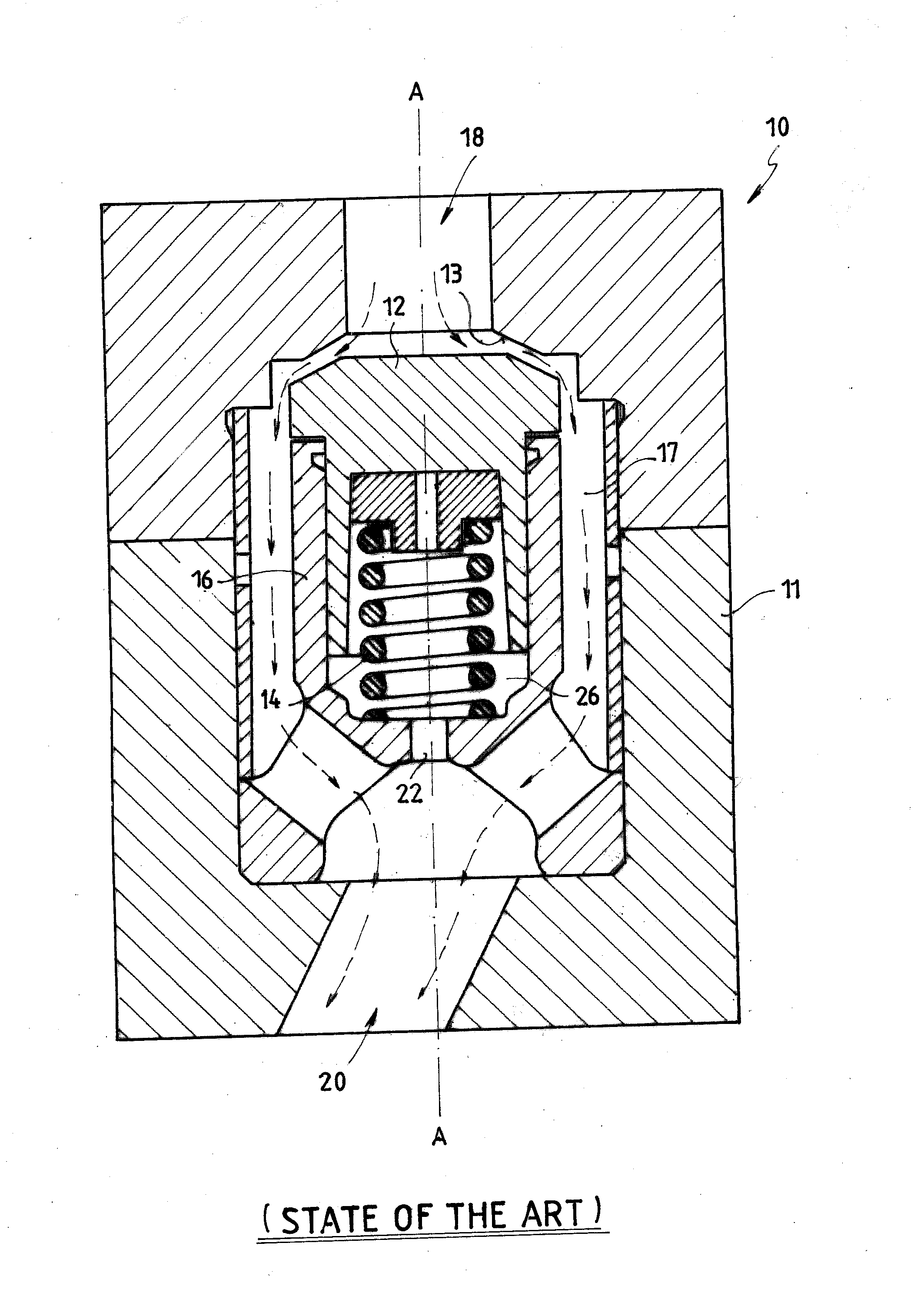
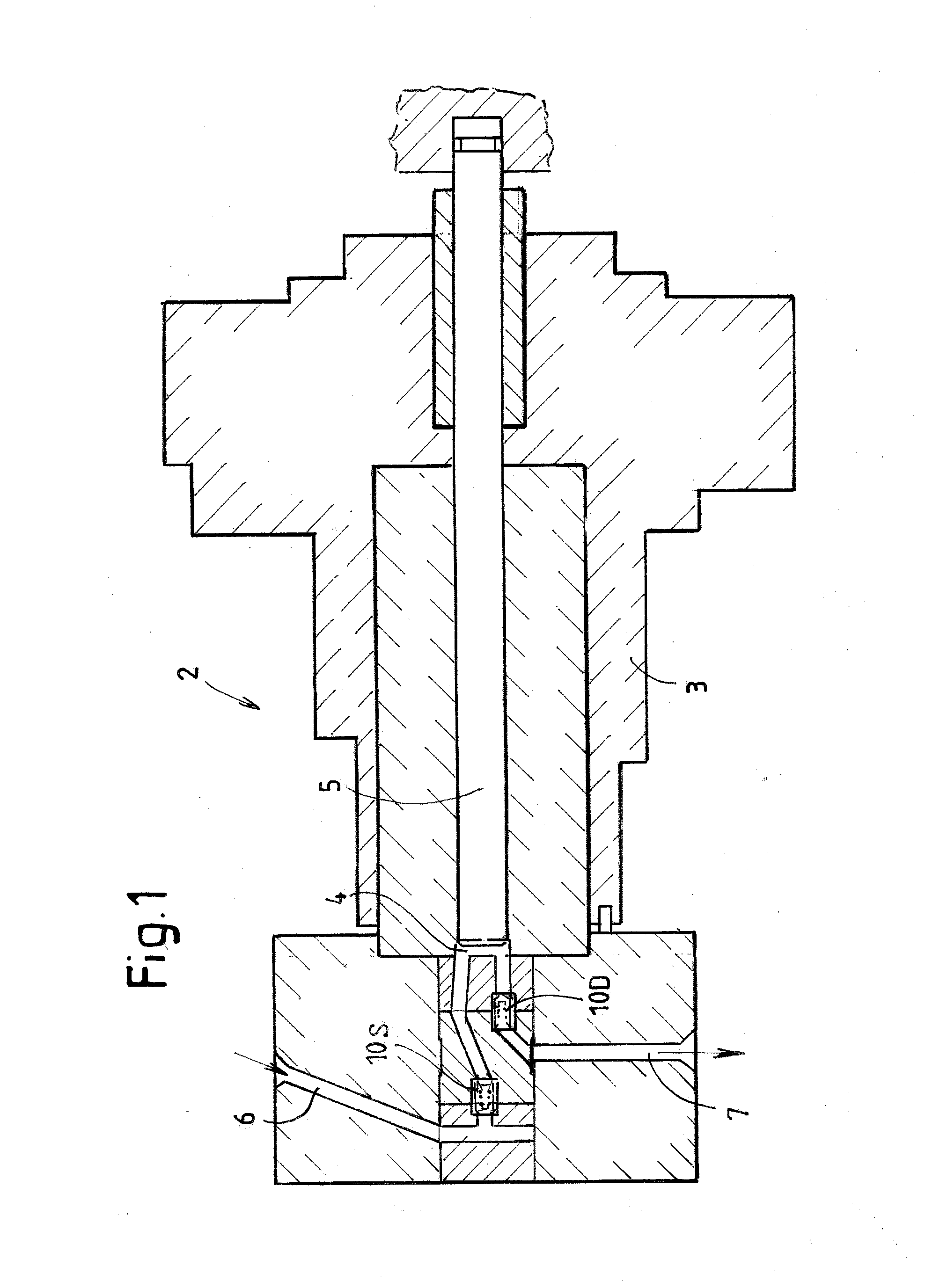
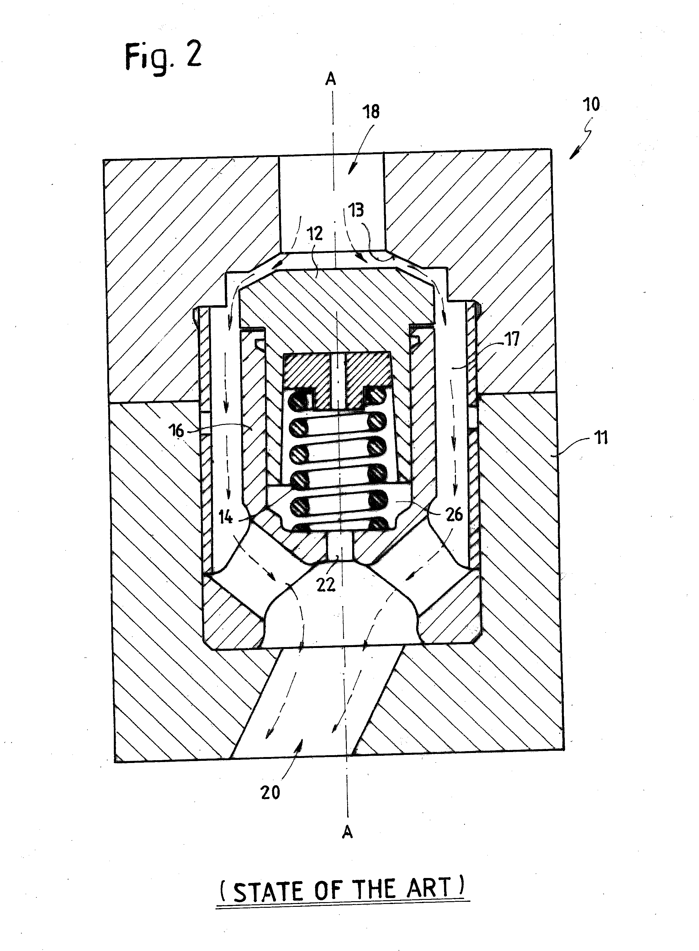
BACKGROUND OF THE INVENTION[0001]The embodiments disclosed herein relate generally to differential pressure valves, i.e. to self-opening and self-closing valves, including a shutter which opens and closes by effect of the differential pressure across the valve. Typical differential pressure valves are reciprocating compressor valves. Some embodiments specifically refer to poppet valves of hyper compressors.[0002]Hyper compressors, those capable of producing gas pressure levels up to or above 3,000 bars, are widely used in industrial application, including, but not limited to, the production of low density polyethylene, or LDPE. The efficient performance of these compressors is controlled at least in part by suction and discharge automatic poppet valves. FIG. 1 illustrates a cutaway of a portion of a hyper compressor 2 of the conventional art comprising two poppet valves 10. FIG. 2 illustrates an enlarged section of one of the conventional poppet valves of the compressor shown in FIG...

Claims


Application Information

Patent Timeline
Patent Type & Authority Applications(United States)
IPC IPC(8): F16K15/00F15B13/04
CPCF04B39/1013F16K15/026F16K47/023Y10T137/7904Y10T137/0318
Inventor BAGAGLI, RICCARDOTOGNARELLI, LEONARDOVOLTERRANI, GUIDOSANESI, MICHELE
Owner NUOVO PIGNONE TECH SRL
Why Eureka
Try Eureka