Wear-resistant structure without damaging matrix and preparation method of wear-resistant structure

A matrix and wear-resistant column technology, applied in the field of wear-resistant structures, can solve problems such as mounting hole swelling, equipment damage, and insufficient wear resistance

Pending Publication Date: 2021-09-10
ZHENGZHOU RES INST OF MECHANICAL ENG CO LTD
View PDF9 Cites 1 Cited by
  • Summary
  • Abstract
  • Description
  • Claims
  • Application Information

AI Technical Summary

Problems solved by technology

[0003] The existing wear-resistant structure mostly adopts the form of installing wear-resistant studs on the matrix to increase the service life. The wear-resistant studs and the matrix generally adopt interference fit or directly surfacing wear-resistant alloy layers on the matrix, but The above combination method has the following problems: if the wear-resistant parts are installed with interference fit, the installation holes on the equipment are easy to burst under the action of instantaneous force, causing damage to the equipment
When adopting the method of surfacing wear-resistant alloy layer directly on the parent body, due to the high hardness and poor toughness of the wear-resistant layer material, the surfacing height is generally controlled at 5-6mm, and at most two layers of surfacing welding are used, and the wear resistance is insufficient; but If the surfacing is too thick, the wear-resistant surfacing layer will easily peel off in a large area, which will seriously affect the use effect

Method used


Image

  • Wear-resistant structure without damaging matrix and preparation method of wear-resistant structure
  • Wear-resistant structure without damaging matrix and preparation method of wear-resistant structure
  • Wear-resistant structure without damaging matrix and preparation method of wear-resistant structure

Examples


Embodiment 1

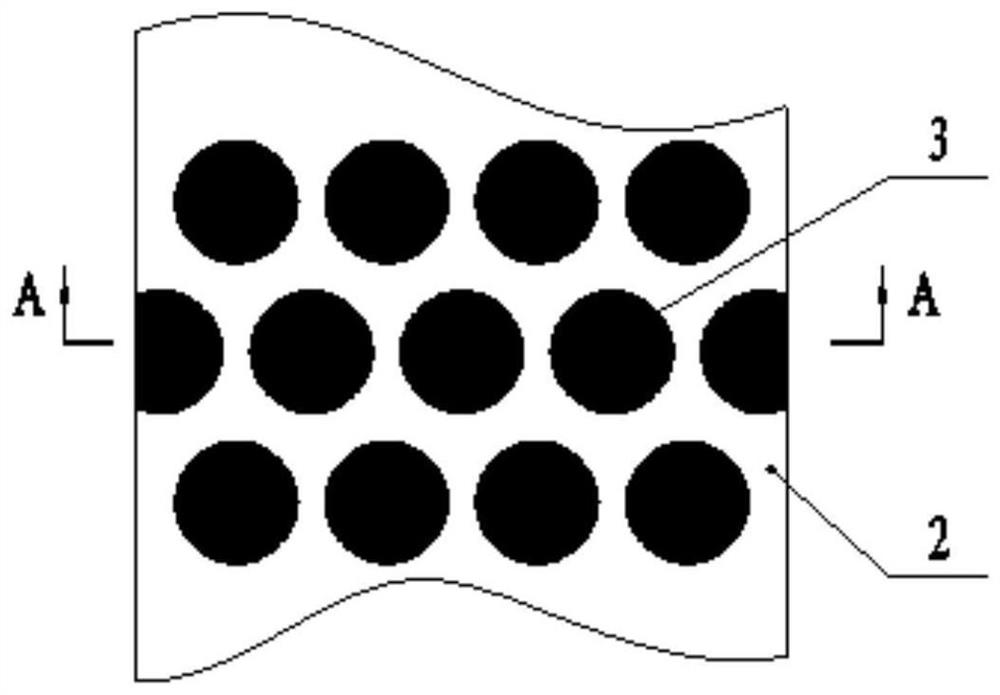
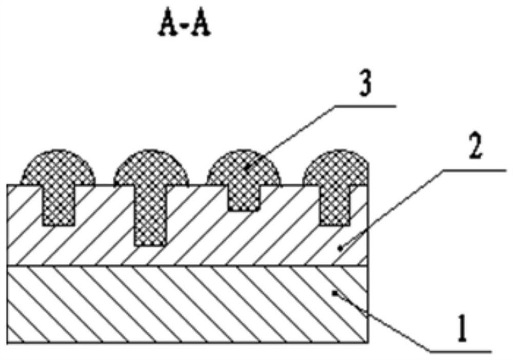
[0036] A wear-resistant structure that does not damage the parent body: including a transition layer 2 and welded wear-resistant studs 3;

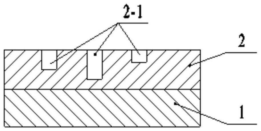
[0037] The transition layer 2 is arranged on the outer surface of the matrix 1 with a thickness of 50mm; the transition layer 2 is provided with a round hole 2-1, the axis of the above round hole 2-1 is perpendicular to the surface of the transition layer 2 and is distributed in a staggered manner, and the center of the round hole 2-1 The distance is 40mm, the diameter is 20mm, the hole depth is 20-40mm, and the depth of round hole 2-1 is not exactly the same;

[0038] The above-mentioned welded wear-resistant studs 3 are set in the round hole 2-1, the part above the transition layer 2 is hemispherical, the diameter of the hemisphere is 30mm, and the height of the parts higher than the transition layer 2 is the same; the welded wear-resistant studs 3 are in the transition Leave a 10mm wide gap on layer 2.

[0039] The preparation method o...

Embodiment 2

[0044] A wear-resistant structure that does not damage the parent body: including a transition layer 2 and welded wear-resistant studs 3;

[0045] The transition layer 2 is arranged on the outer surface of the matrix 1 with a thickness of 40mm; the transition layer 2 is provided with round holes 2-1, the axes of the above round holes 2-1 are perpendicular to the surface of the transition layer 2 and are distributed in a staggered manner, and the center of the round holes 2-1 The distance is 65mm, the diameter is 30mm, the hole depth is 20-35mm, and the depth of round hole 2-1 is not exactly the same;

[0046] The above-mentioned welded wear-resistant studs 3 are set in the round hole 2-1, the part above the transition layer 2 is hemispherical, the diameter of the hemisphere is 60 mm, and the height of the parts higher than the transition layer 2 is the same; the welded wear-resistant studs 3 are in the transition A 5 mm-wide slit was formed on the layer 2 .

[0047] The prepa...

Embodiment 3

[0052] A wear-resistant structure that does not damage the parent body: including a transition layer 2 and welded wear-resistant studs 3;

[0053] The transition layer 2 is arranged on the outer surface of the flat plate 1 with a thickness of 50mm; the transition layer 2 is provided with a round hole 2-1, the axis of the above round hole 2-1 is perpendicular to the surface of the transition layer 2 and is distributed in a staggered manner, and the center of the round hole 2-1 The distance is 47mm, the diameter is 35mm, the hole depth is 20-25mm, and the depth of round hole 2-1 is not exactly the same;

[0054] The above-mentioned welded wear-resistant stud 3 is set in the round hole 2-1, the part above the transition layer 2 is hemispherical, the diameter of the hemisphere is 45mm, and the height of the part higher than the transition layer 2 is the same; the welded wear-resistant stud 3 is in the transition A 2 mm wide slit was formed on the layer 2 .

[0055] The preparatio...


PUM

PropertyMeasurementUnit
thicknessaaaaaaaaaa
diameteraaaaaaaaaa
tensile strengthaaaaaaaaaa

Abstract

The invention discloses a wear-resistant structure without damaging a matrix. The wear-resistant structure comprises a transition layer overlaid on the matrix, a round hole with the depth smaller than the thickness of the transition layer and incompletely consistent depth is processed in the transition layer, and a welding wear-resistant stud is overlaid in the round hole. The transition layer has better toughness and processability, and the round holes are formed in the transition layer, so that the transition layer is not easy to crack; the transition layer with good toughness is matched with the welding wear-resistant column nails with high strength and good wear resistance to form a soft and hard staggered structure, so that the impact stress of a hard material on the wear-resistant structure can be relieved; the welding wear-resistant stud is not in direct contact with the matrix, so that direct damage to the matrix can be effectively reduced; and the external height of the welded wear-resistant stud nail is consistent but discontinuous, so that the problem that a continuous wear-resistant alloy layer formed by depositing wear-resistant alloy on the matrix in the prior art is easy to crack is effectively solved. The invention further discloses a preparation method of the wear-resistant structure, the service cycle of the wear-resistant structure is effectively prolonged, the matrix is protected from being damaged, and the wear resistance is improved.

Description

technical field [0001] The invention relates to a wear-resistant structure, in particular to a wear-resistant structure which does not damage the matrix and a preparation method thereof. Background technique [0002] At present, wear-resistant structures are widely used in metallurgy, chemical industry, mining, and coal industry, and have the characteristics of energy saving, consumption reduction, and high degree of automation. The wear-resistant structure is applied to the powder production line of grading and dispersing, which can improve the production effect of the subsequent ball mill. Common roller presses, wear-resistant plates, etc. all involve the installation and use of wear-resistant structures. After the roller press and wear-resistant plate are installed and used, they work continuously for a period of time, and the wear-resistant layer on the surface of the parent body is worn away. The wear of the roller surface limits its advantages, greatly reducing the ou...

Claims


Application Information

Patent Timeline
Patent Type & Authority Applications(China)
IPC IPC(8): B02C4/30B02C17/18B23P15/00C22C38/02C22C38/04C22C38/56C22C38/58
CPCB02C4/305B02C17/18C22C38/58C22C38/02C22C38/04C22C38/56B23P15/00
Inventor 黄智泉张海燕杨威潘健魏建军张永生魏炜高站起李恒
Owner ZHENGZHOU RES INST OF MECHANICAL ENG CO LTD
Why Eureka
Try Eureka