Plowing machine and plowing method thereof

A farming machine and frame technology, which is applied in the field of farming machines and tools, can solve the problems of increased tillage depth, easy breakage, unstable tillage depth, etc., and achieve the effects of deepened tillage depth, stable operation, and good stress effect

Inactive Publication Date: 2015-11-04
张培坤
View PDF7 Cites 2 Cited by
  • Summary
  • Abstract
  • Description
  • Claims
  • Application Information

AI Technical Summary

Problems solved by technology

[0004] The existing rotary tiller mounted on the walk-behind tractor generally has a radius of rotation of 210mm, deducting the radius of the transmission box of 90mm, and theoretically the maximum plowing depth can reach 120mm. Fracture, in general, the actual plowing depth is 100mm
That is to say, for the arable land in the vast mountainous and hilly areas, if the plowing radius of the coulter is simply increased or the plow plow and disc plow are used to achieve the purpose of deep plowing, the failure rate of the equipment will increase with the increase of plowing depth. Significantly improved, and the device that produces resistance in the existing micro-tillage machine is generally a resistance bar, which generates a certain resistance by inserting the resistance bar into the ground, and slows down the speed of the micro-tillage machine, thereby increasing the depth of cultivation. However, the resistance bar is actually There are many inconveniences in use. The resistance generated by the resistance rod is affected by the soil properties, and the resistance is difficult to control, resulting in unstable plowing depth, and it is easy to wrap the vegetation branches during the travel of the resistance rod, which affects the use.

Method used


Image

  • Plowing machine and plowing method thereof
  • Plowing machine and plowing method thereof
  • Plowing machine and plowing method thereof

Examples


Embodiment 1

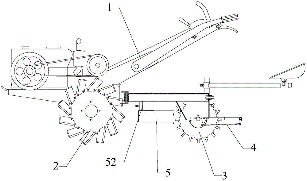
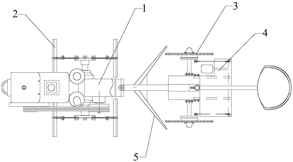
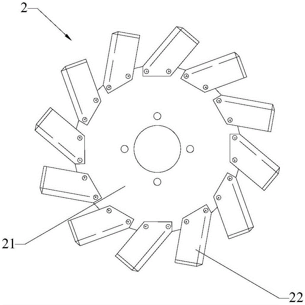
[0041] Please refer to Figure 1 to Figure 6 Shown, embodiment one of the present invention is:

[0042]An agricultural machine and its farming method, comprising a frame 1, a coulter wheel 2, a resistance wheel 3 and a scraping device 5, the coulter wheel 2 is arranged in front of the resistance wheel 3, and the coulter wheel 2 includes a flange Disk 21 and a plurality of coulters 22, the coulters 22 are evenly installed on the outer edge of the flange plate 21, the adjacent coulters 22 are installed in reverse, the resistance wheel 3 is provided with a braking device 4, the scraper The leveling device 5 is arranged between the coulter wheel 2 and the resistance wheel 3, and the leveling device 5 includes a vertically arranged scraping plate 51 and a height adjuster 52, and the one scraping plate 51 is symmetrically fixed on the On both sides of the frame 1, the scraper plate 51 is arranged inclined to the rear of the agricultural machine, the scraper plate 51 is connected t...


PUM


Abstract

The invention relates to the field of plowing machines and aims to provide a plowing machine and a plowing method thereof. The plowing machine comprises a rack, plow coulter wheels and resistance wheels and is characterized in that the plow coulter wheels are arranged in front of the resistance wheels, each plow coulter wheel comprises a flange plate and multiple plow coulters, the plow coulters are uniformly mounted on the outer edge of each flange plate, every two adjacent plow coulters are reversely mounted, and a brake device is arranged on each resistance wheel. The plowing machine and the plowing method have the advantages as follows: the plow coulters are arranged on the plow coulter wheels, all the weight of a walking tractor are borne by the plow coulter wheels during plowing, sufficient downward pressure is generated, meanwhile, the brake devices on the resistance wheels brake, certain drag resistance is generated, the plow coulter wheels perform semi-sliding motions in soil under the simultaneous action of downward pressure and drag resistance of the walking tractor to drive the plowing machine to move forward and plane soil below the plow coulter wheels, and accordingly, the plowing depth is increased.

Description

technical field [0001] The invention relates to the field of farming machines, in particular to a farming machine and a farming method thereof. Background technique [0002] In agricultural production, dryland crops must be plowed in winter before sowing or transplanting. In order to be more conducive to crop growth, the general agronomic requirement is that the plowing depth should reach 200mm, which is conducive to the growth of crop roots and soil moisture conservation. To ensure the yield and quality of crops, this is the so-called deep plowing operation in agricultural production. [0003] At present, my country's agricultural machinery only has plows and disc plows that are towed by high-horsepower four-wheel tractors to operate in plain areas. Part of the farmland in mountainous and hilly areas plowed by small-scale agricultural machinery has shallower and shallower plowing layers, underdeveloped root systems of crops, and poor drought and lodging resistance. Therefo...

Claims


Application Information

Patent Timeline
Patent Type & Authority Applications(China)
IPC IPC(8): A01B33/02A01B33/10
Inventor 张培坤王又沐张心伟
Owner 张培坤
Why Eureka
Try Eureka