
System Adapted For One or More Electrically Propellable Vehicles ( Rail Structure)

a technology of electrically propellable vehicles and rail structures, applied in the direction of power rails, connecting contact material, transportation and packaging, etc., can solve problems such as electrical safety risks

Active Publication Date: 2013-01-24
ELWAYS AB
View PDF13 Cites 19 Cited by
  • Summary
  • Abstract
  • Description
  • Claims
  • Application Information

AI Technical Summary

Benefits of technology

The patent describes a device that has a mechanism that can elevate a contact out of its track when it reaches its maximum limit. This mechanism is controlled by a control system. The technical effect of this device is to provide a safety mechanism that prevents the contact from hitting its maximum limit and causing damage.

Problems solved by technology

In this way, if the vehicle turns off the roadway and therefore does not enter the next set of conductors or strips, the next set of conductors or strips will not detect the presence of the vehicle and therefore will shut off the power supply shortly after it has been turned on.
Thus, standing on one of the conductors or strips will not complete any circuit and therefore little or no current will flow through a person standing on one of the copper conductors or strips.
For example, the lower the standard DC voltage selected, the lower will be the perceived electrical safety risk, the lower will be the actual energy leakage, when a roadway is wet and the conductors or strips are on and the fewer the number of battery cells in each vehicle to provide an on-board power supply.

Method used


Image

  • System Adapted For One or More Electrically Propellable Vehicles ( Rail Structure)
  • System Adapted For One or More Electrically Propellable Vehicles ( Rail Structure)
  • System Adapted For One or More Electrically Propellable Vehicles ( Rail Structure)

Examples


Embodiment Construction

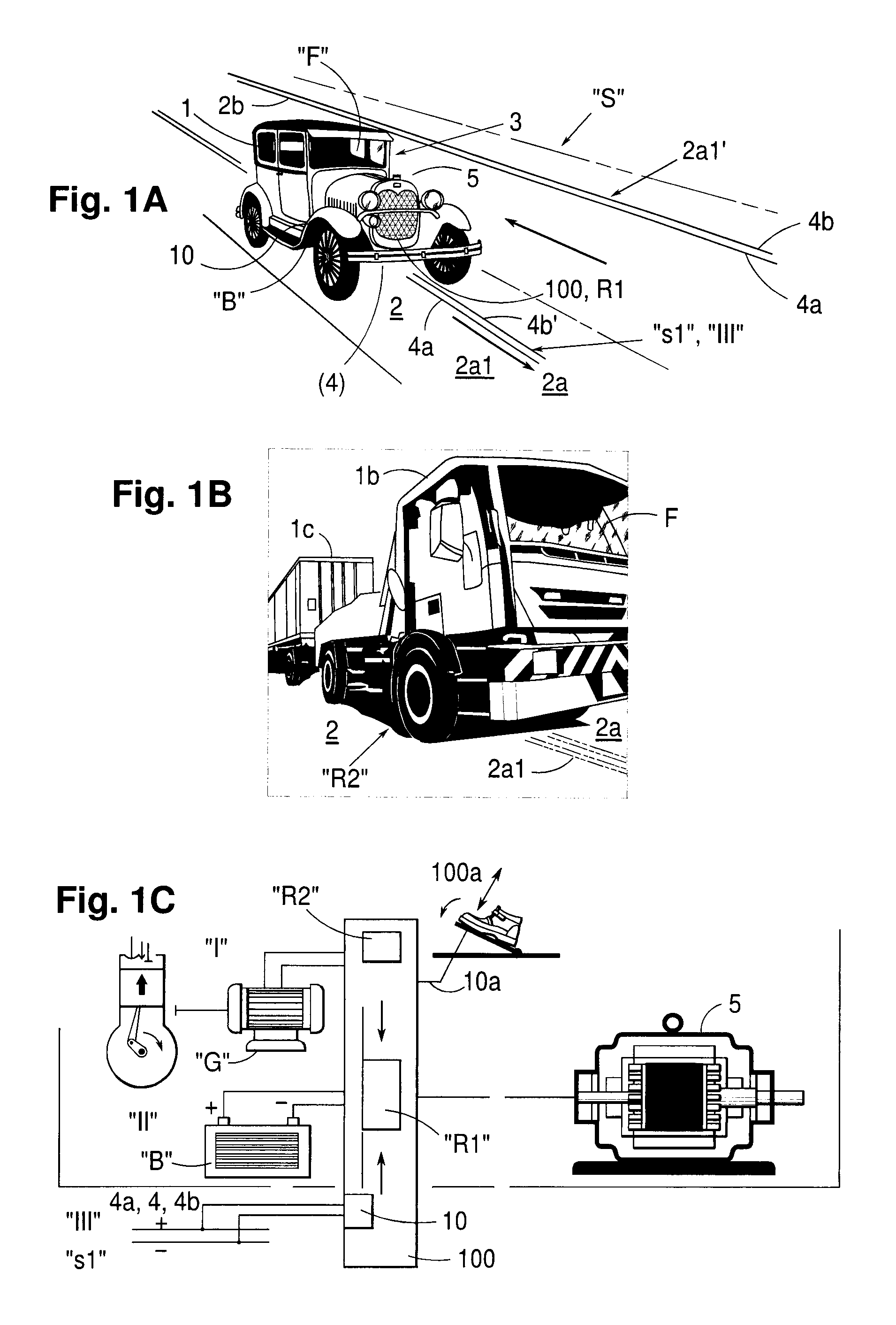
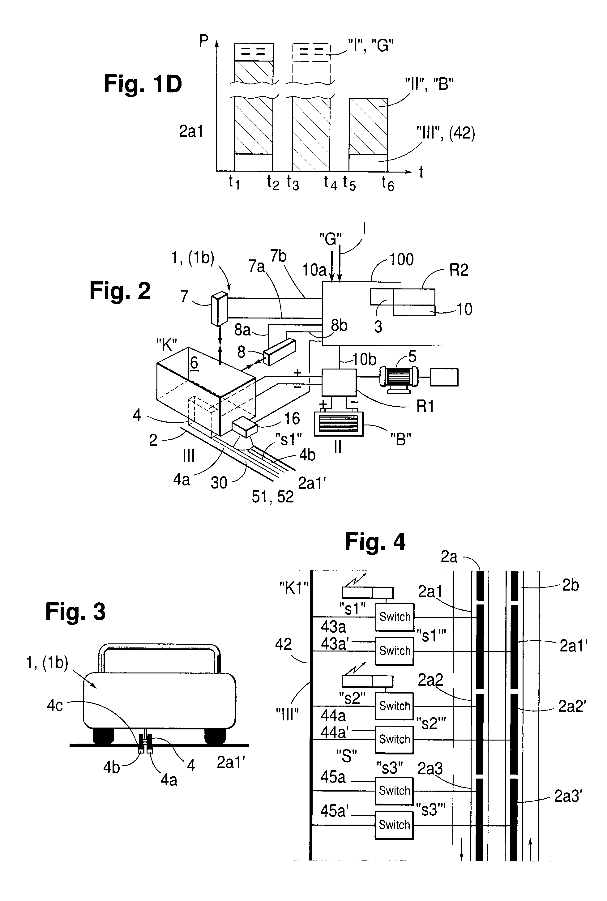
[0214]By way of introduction it shall be mentioned that in the following description of presently proposed embodiments exhibiting the significant characteristics related to the invention and being clarified by the figures, illustrated in the accompanying drawings, we have chosen terms and specific terminology with the purpose of thereby primarily clarifying the concept of the actual invention.

[0215]However, in this connection it should be noted that the terms chosen here shall not be seen as limiting solely to the terms utilized and chosen here and it should be understood that each such chosen term is to be construed such, that it in addition will be able to include all technical equivalents which operate in the same manner or essentially the same manner so as thereby to be able to achieve the same or essentially the same purpose and / or the same technical result.

[0216]Thus, with reference to the accompanying drawings, the basic prerequisites of the present invention are shown schema...


PUM


Abstract

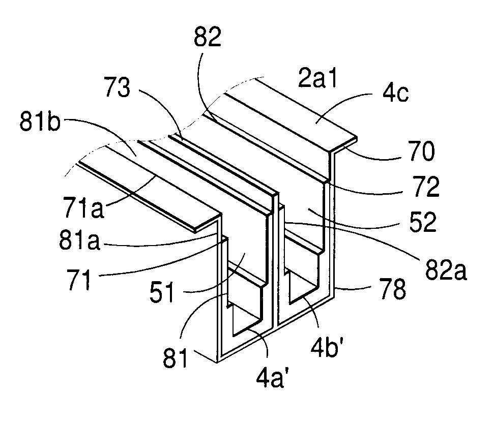
This invention concerns a rail structure (70, 71, 72, 73) in a vehicle-related system (S) for driving an electric and by one or more batteries conveyable vehicle (1) along a stretch of a track in a roadway section (2a1) and related to a roadway, comprising (a″) by one or more individual electric motors (5) drivable vehicles (1), and “b” a plurality of roadway sections (2a1, 2a) which may subdivide the stretch of roadway. Said tracks (51, 52) are in a cross section oriented in parallel in a rail structure (70), said rail structure (70) having external, of metal made, wall sections (71, 72) and a partition (73) separating the external wall sections. A first conductor surface ( ), which may be subjected to voltage, is allotted a lower portion for a first track (51). A second conductor surface (4b), which may be subjected to voltage, is allotted a lower portion for a second track (52).

Description

TECHNICAL FIELD OF THE INVENTION[0001]This invention refers generally to a rail structure having at least one, usually two tracks, each track is enclosing an electric conductor exposing a conductor surface, adapted for a cooperation with a current collector arrangement, which is adapted to be able to elevate and lower contact means and / or a contact device, in the for of current collectors, with each vehicle being adapted to a system appropriate for electrically propellable vehicles and more particularly to such system in which i.a. one or more batteries and / or a set of batteries for power adaptation and energy storage are intended for being able to propel the vehicle rolling along a stretch of a roadway.[0002]Systems of this type are based on utilizing a specifically designed stretch of the road or roadway wherein the upper surface of this stretch of the roadway exhibits at least one track in the form of groove and in which track two or more parallel electric conductors or strips wi...

Claims


Application Information

Patent Timeline
IPC IPC(8): B60M1/34
CPCB60L5/40B60L2200/26B60M1/36B60M1/34
Inventor ASPLUND, GUNNAR
Owner ELWAYS AB
Learn More