Dispenser with optical keying system

a technology of optical keying and dispenser, which is applied in the direction of liquid transfer devices, volume meters, instruments, etc., can solve the problems of presenting contamination and health concerns, and incorrect materials may be devastating to the health of users, and the service is messy and difficul

Inactive Publication Date: 2013-01-24
GOJO IND INC
View PDF17 Cites 47 Cited by
  • Summary
  • Abstract
  • Description
  • Claims
  • Application Information

AI Technical Summary

Benefits of technology

[0011]It is another aspect of the present invention to provide a dispenser with an optical keying system that can be recycled and used with recyclable refill containers.

Problems solved by technology

While dispensers may directly hold a quantity of material, such as soap, in a reservoir, such dispensers have been found to be both messy and difficult to service, while also presenting contamination and health concerns.
That is, in some circumstances dispenser manufacturers may be concerned with ensuring that the appropriate refill container (type of product, concentration, material form, etc.) is inserted in the correct dispenser housing, as the use of the incorrect material may be devastating to the health of the user and those who come in contact with the user.
For example, mechanical keys are often easily removed or altered, allowing unauthorized refill containers to be readily installed into a dispenser, while also causing the manufacturer / distributor to lose the ability to control the quality of the material used in the dispenser.
Mechanical keying systems also require the manufacturer to design keys for multiple types of dispensers and refill containers, which requires significant tooling costs that are incurred by the manufacturer.
This results in significant inventory costs for maintaining refill containers with various keys and also generates lead times for manufacturing such refill containers, which may be substantially long.
Finally, in the event that a particular keying device for a dispenser is lost or damaged, it may create difficult circumstances to determine which type of keying configuration is needed for the refill containers.
Moreover, current keying systems are configured with non-recyclable refill containers that once used are thrown away, thus contributing to waste in landfills and increased disposal costs.

Method used


Image

  • Dispenser with optical keying system
  • Dispenser with optical keying system
  • Dispenser with optical keying system

Examples


Embodiment Construction

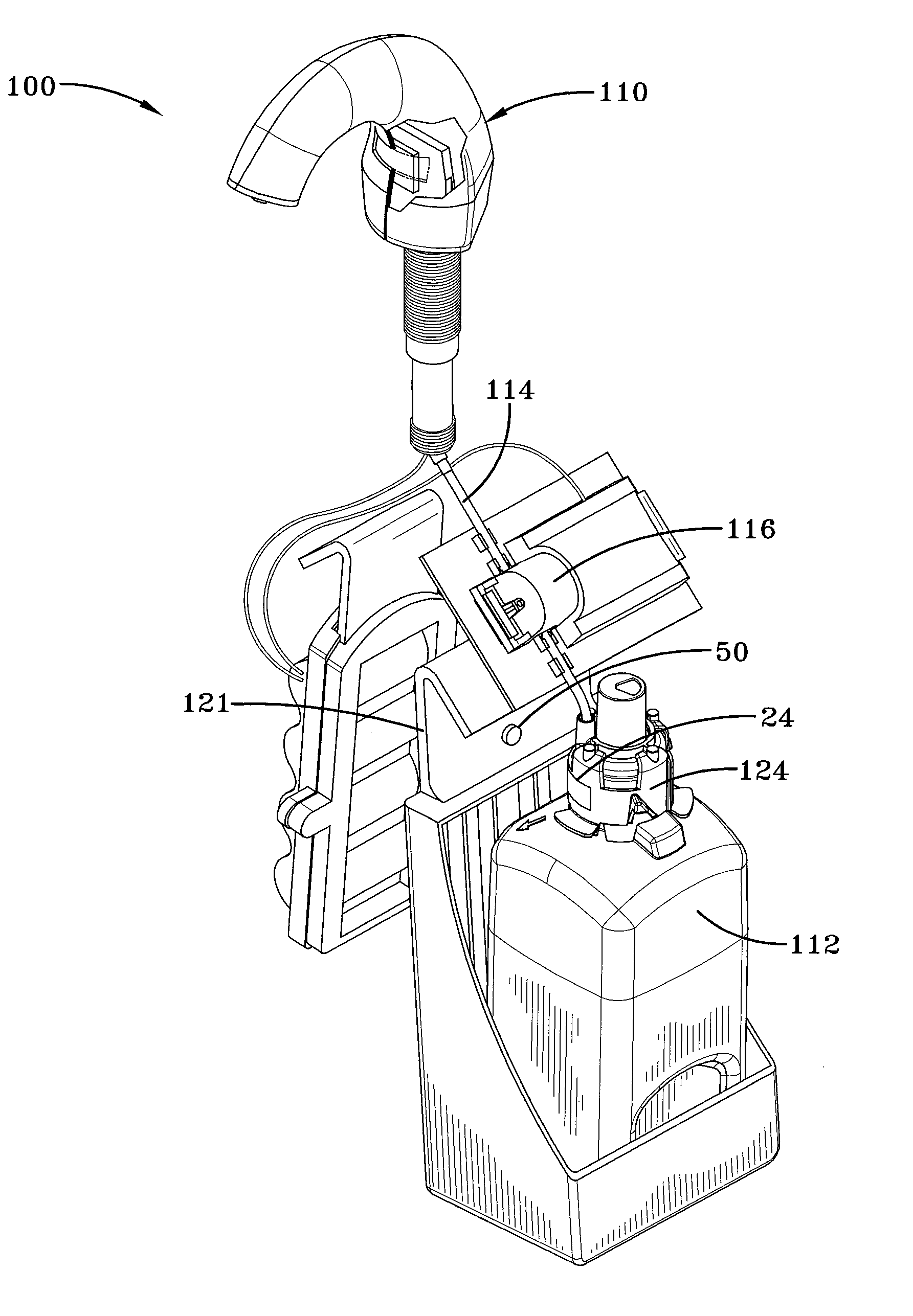
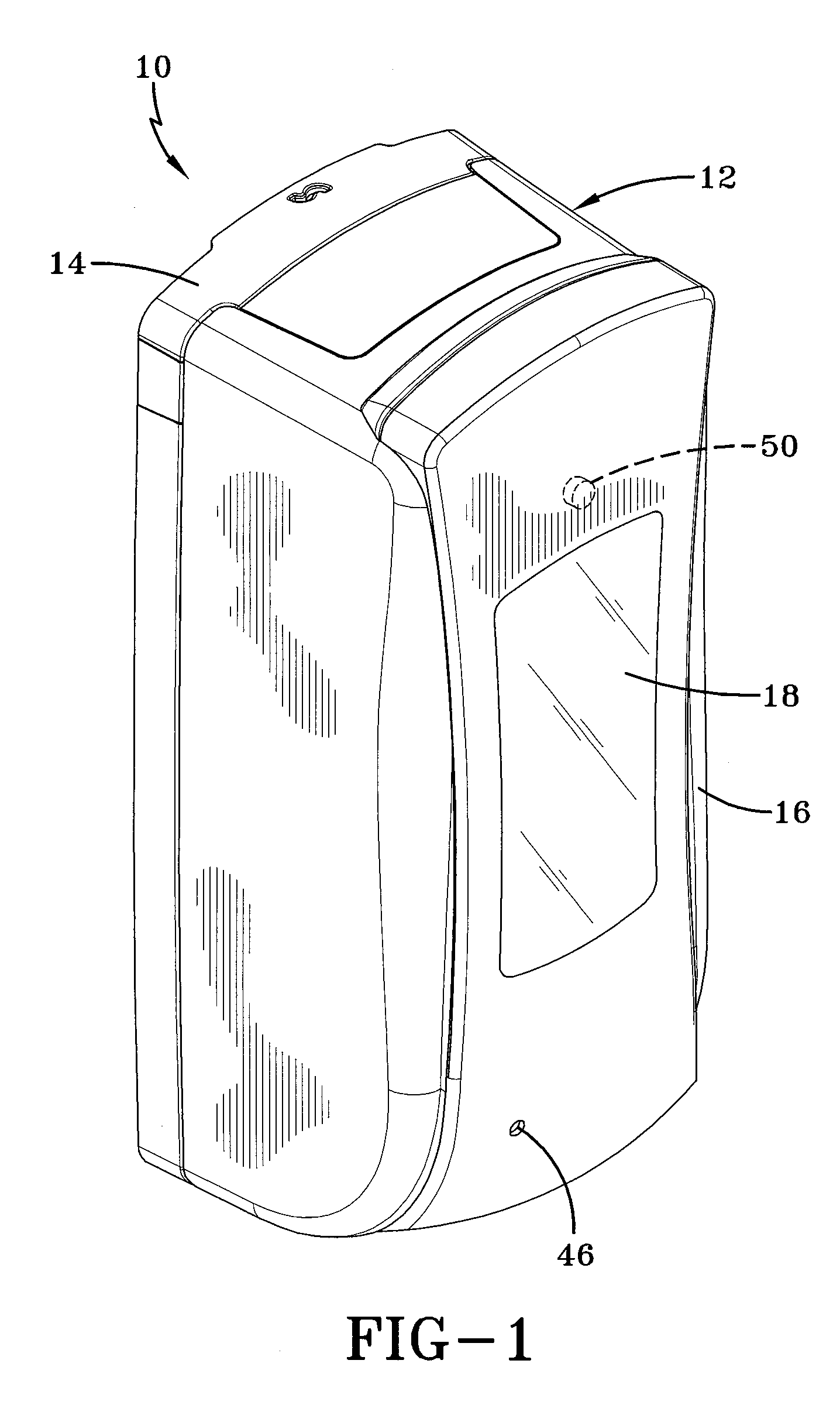
[0028]A dispenser having an optical keying system is generally referred to by the numeral 10, as shown in FIGS. 1-5 of the drawings. The dispenser 10 includes a housing 12, which includes a back plate 14 adapted to be secured to a vertical surface, and a cover 16 that is pivotable relative to the back plate 14. The cover 16 permits access to the internal components of the dispenser 10 and may include a window 18 so that the interior of the dispenser 10 can be viewed. As such, the cover 16 may be removed to install or remove a refill container 22 that contains a label 24 having indicia 26 disposed thereon, which defines various predetermined reference codes used in part to determine if the refill container 22 is authorized for use with the dispenser 10. It should be appreciated that the term “indicia” as used herein is defined as any microscopic mark, indentation, or the like, such as one or more microscopic printed dots, that cannot be viewed by the human eye, but is capable of bein...


PUM


Abstract

A dispenser with an optical keying system includes a housing that is configured to carry a removable refill container that contains an amount of material, such as soap, for example. The removable refill container includes microscopic indicia that is visually-imperceptible to a human, which includes an authorization code, as well as a reference code that identifies various attributes associated with the refill container, such as its size, material type, and date of manufacture. Finally, the dispenser includes an optical sensor that is configured to read the authorization code defined by the microscopic or visually-imperceptible indicia to determine whether the refill container is authorized for use with the dispenser.

Description

CROSS-REFERENCE TO RELATED APPLICATION[0001]This application claims the benefit of U.S. Provisional Application No. 61 / 510,355, filed Jul. 21, 2011, the contents of which are incorporated herein by reference.TECHNICAL FIELD[0002]The present invention is generally directed to dispensing systems. In particular, the present invention is directed to dispensers that are keyed to allow only authorized refill containers to be installed and used therein. More specifically, the present invention is directed to an optical keying system for a dispenser that uses an optical sensor to read microscopic indicia disposed on a refill container that is visually imperceptible to the human eye in order to authenticate the refill container.BACKGROUND OF THE INVENTION[0003]Dispensers used to dispense various liquid materials, such as soap, antibacterial cleansers, powder, aerosols, disinfectants, lotions, and the like are used in various contexts, including restaurants, factories, hospitals, and bathroom...

Claims


Application Information

Patent Timeline
Patent Type & Authority Applications(United States)
IPC IPC(8): B65D83/00
CPCA47K5/1214A47K2005/1218A47K5/1217
Inventor PELFREY, KEITH A.
Owner GOJO IND INC
Why Eureka
Try Eureka