System and method for fuel cell material x-ray analysis

a fuel cell and x-ray technology, applied in the direction of material analysis using wave/particle radiation, instruments, nuclear engineering, etc., can solve the problems of tedious and difficult process, general destructive device image processing, etc., to accelerate the development of sofc technology, improve reliability, and reduce development time

Active Publication Date: 2009-03-03
CARL ZEISS X RAY MICROSCOPY
View PDF4 Cites 42 Cited by
  • Summary
  • Abstract
  • Description
  • Claims
  • Application Information

AI Technical Summary

Benefits of technology

[0005]The present invention concerns the use of an imaging technology for fuel cells based on x-ray microscopy. The large penetration depth of x-ray radiation enables imaging through the ROI without sectioning, and when used in combination with the tomography technique used in medical CT scans, the exact three dimensional (3D) structure of a sample can be obtained non-destructively, even while the device is in operation. This technology can further take advantage of the strong dependence of the x-ray absorption on material type and energy to distinguish the four major material types: cathode, electrolyte, air, and low-Z contaminants such as sulfur. This means that that the geometry of porous structures in the TPB can be directly measured from the 3D images to understand a SOFC's electrochemical state and predict its performance. This represents a metrology capability that is important for the development of fuel cell technology. By providing the most direct and relevant information on the exact operating conditions of the device, it has the potential to significantly reduce the development time and improve the reliability.
[0006]In one example, a metrology system images the electro-chemical interaction areas of solid-oxide fuel cells (SOFC) in-situ. This system takes advantage of both the penetrating power and elemental absorption contrast of hard x-ray radiation to image the internal interaction areas in a SOFC. Combined with computer tomography (CT) technique, the 3D morphology of the interaction volume can be obtained in-situ at 50-nm 3D resolution, and different material compositions can also be determined. Consequently, the exact aging mechanism can be tracked and analyzed dynamically while the device is in operation. This system provides the most direct and relevant information on the exact operating conditions of the device, having the potential to significantly accelerate the development of the SOFC technology and reduce the time-to-market.

Problems solved by technology

But because of the shallow penetration depth of electrons, the imaging processes are generally destructive to the device, as the region of interest (ROI) must be mechanically cross-sectioned to reveal buried structures.
This is a tedious and difficult process that is prone to introducing artifacts, particularly with hard and porous ceramic materials used in fuel cells.
Furthermore, electron microscopy only provides a surface picture and does not reveal the pore connectivity.

Method used


Image

  • System and method for fuel cell material x-ray analysis
  • System and method for fuel cell material x-ray analysis
  • System and method for fuel cell material x-ray analysis

Examples


Embodiment Construction

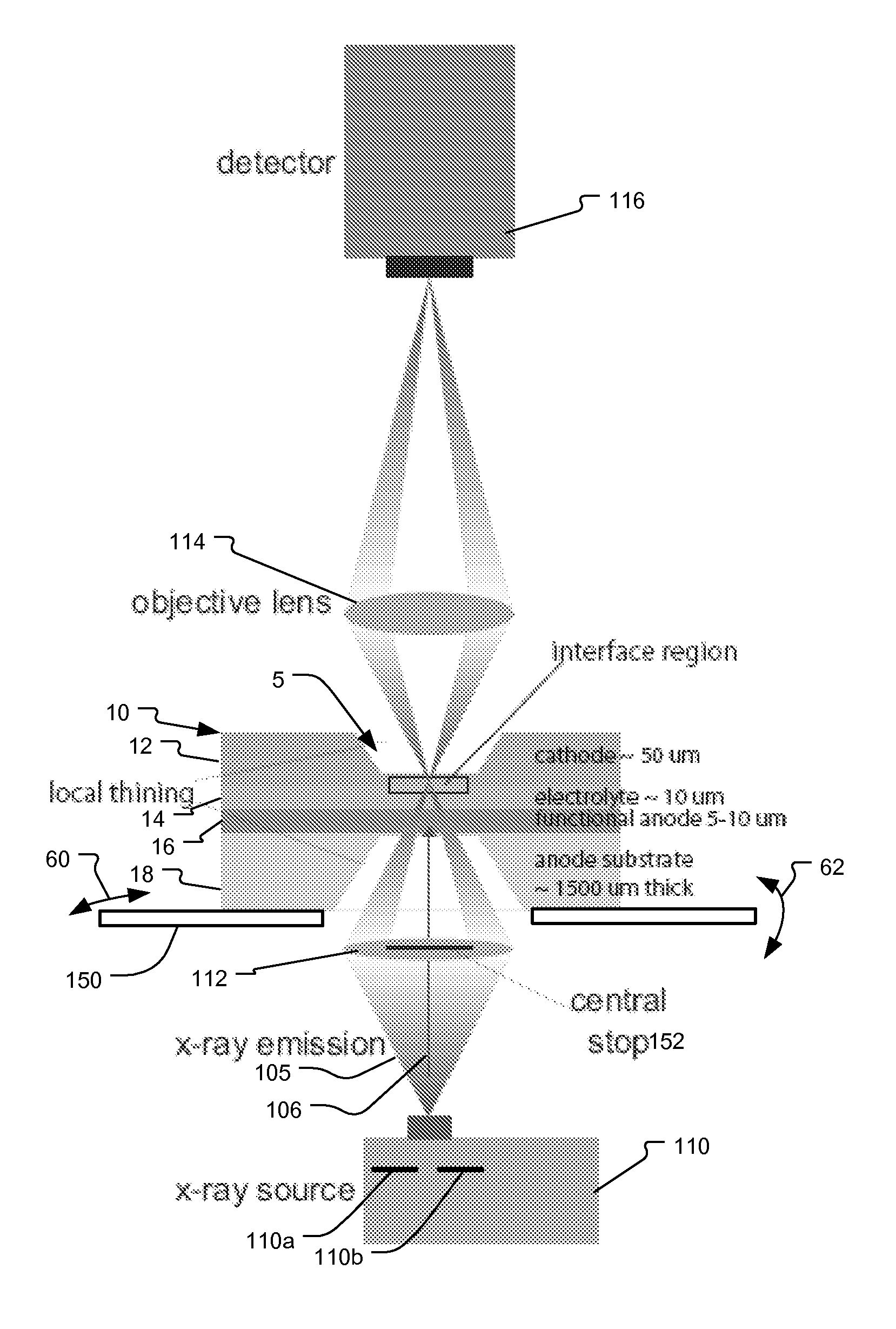
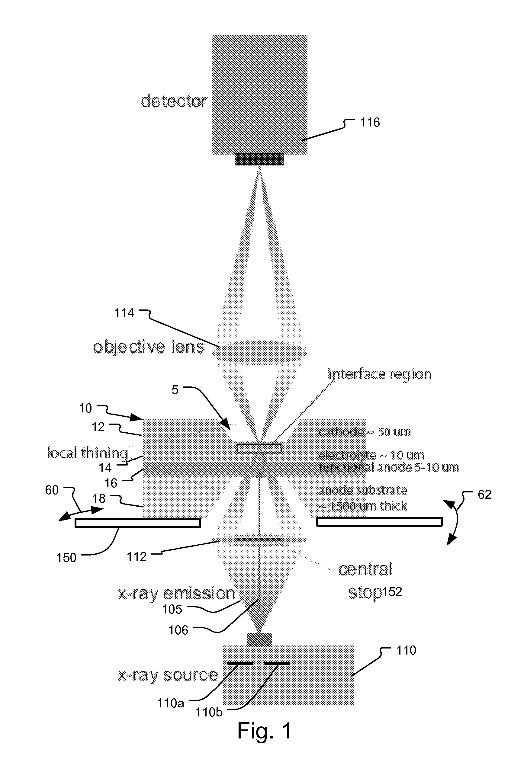
[0013]The disclosed tool is designed to nondestructively image the three-dimensional structure of the interface area of LSM / YSZ at 1-100 nm resolution while being able to distinguish four different materials: LSM, YSZ, sulfur, and air (empty gap space). There are two important elements to this approach: (1) how to resolve the structures in 3D and (2) how to distinguish different materials.

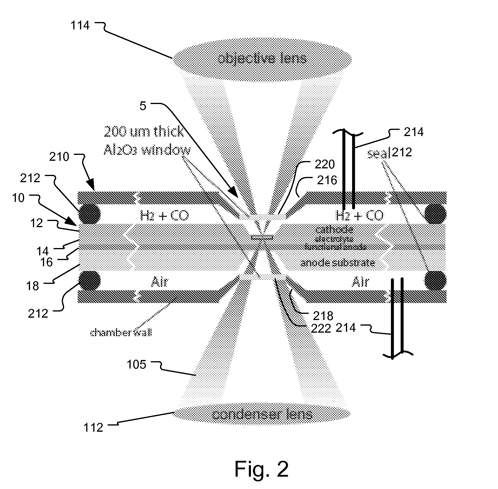
[0014]FIG. 1 shows an x-ray microscope (TXM) 100. In a setup similar to a conventional visible light microscope, x-ray microscope 100 comprises an x-ray source 110, condenser lens 112, objective lens 114, and an area detector system 116. This microscope 100 is used to image a SOFC anode substrate 10. In one example, the anode substrate 10 comprises a cathode layer 12 (thickness approximately 50 micrometers (μm)), an electrolyte layer 14 (thickness approximately 10 μm), functional anode layer 16 (thickness approximately 5-10 μm), and anode substrate 18 (thickness approximately 1500 μm).

[0015]Prefera...


PUM


Abstract

An imaging technology for fuel cells is based on x-ray microscopy. A metrology system images the electro-chemical interaction areas of solid-oxide fuel cells (SOFC) in-situ. This system takes advantage of both the penetrating power and elemental absorption contrast of hard x-ray radiation to image the internal interaction areas in a SOFC. The technology can further take advantage of the strong dependence of the x-ray absorption on material type and energy to distinguish the four major material types: cathode, electrolyte, air, and low-Z contaminants such as sulfur.

Description

BACKGROUND OF THE INVENTION[0001]Fuel cell devices convert chemical energy directly into electrical energy without combustion. The immediate benefit is much higher energy conversion efficiency and the drastic reduction of pollutants. Solid-oxide fuel cells (SOFC), in particular, are able to utilize existing widely used hydrocarbon fuel to simultaneously generate thermal and electrical power with combined heat and power (CHP) efficiency of over 80%. In comparison, internal-combustion engines (ICE) provide 25-30% efficiency with most of the energy loss in the form of exhaust heat and pollution. SOFC technology therefore can significantly reduce the fuel consumption as well as pollutant emission of vehicles, and without the need of exotic fuels.[0002]A critical step in making these devices practical is developing electrode and electrolyte components with high efficiency and high resistance to aging and contamination. The electrochemical reactions occur in a narrow zone along the three-...

Claims


Application Information

Patent Timeline
Patent Type & Authority Patents(United States)
IPC IPC(8): G21K7/00
CPCG01N23/04
Inventor WANG, YUXINYUN, WENBING
Owner CARL ZEISS X RAY MICROSCOPY
Why Eureka
Try Eureka