Convergence Zone

a technology of global navigation satellite and receiver, applied in the direction of satellite radio beaconing, measurement devices, instruments, etc., can solve the problems of inability of the receiver to determine the distance between the satellite and the receiver with sufficient accuracy, and the receiver may also be unable to recognise the start of a sub-fram

Inactive Publication Date: 2013-01-24
QUALCOMM TECH INT
View PDF9 Cites 4 Cited by
  • Summary
  • Abstract
  • Description
  • Claims
  • Application Information

AI Technical Summary

Benefits of technology

[0035]According to a third embodiment of the invention, there is provided a computer-readable medium encoded with instructions, that when executed by an apparatus for calculating the location of a receiver in a satellite navigation system, causes the apparatus to calculate a location of the receiver by means of an algorithm that utilises an estimate of receiver location and / or an estimate of absolute time, and to perform the calculation in such a way as to extend a convergence zone within which the algorithm is capable of generating the correct location for the receiver despite an error in the estimate(s).

Problems solved by technology

However, in practice GPS receivers use signals from four or more satellites to determine an accurate three-dimensional location solution because an offset between the receiver clock and GPS time introduces an additional unknown into the calculation.
If the satellite signal reception is poor (commonly known as weak signal conditions), or if the receiver only receives a short burst of the signal, the receiver may not be able to decode the TOW information.
Without this information, the GPS receiver may be unable to determine the distance between it and the satellite with sufficient accuracy because the receiver will not know the time when the signalling event was transmitted.
Under weak signal conditions or briefly glimpsed signals, the receiver may also be unable to recognise the start of a sub-frame since it may not be able to decode the TLM.
However, since both the PN code in the signal and the locally generated replica code are of finite length in space (known as the code wavelength), the correlation operation can only identify a part of the total time shift.
Uncorrected, these clock biases introduce significant errors into the location calculation.
For example, U.S. Pat. No. 7,064,709 explains that calculating the integer number of milliseconds using estimated pseudo-ranges is not always sufficiently accurate and instead proposes a method whereby a common transit delay, represented as an number of integer milliseconds, is inserted as one of the unknowns to be determined as part of the location calculation.

Method used


Image

  • Convergence Zone
  • Convergence Zone
  • Convergence Zone

Examples


Embodiment Construction

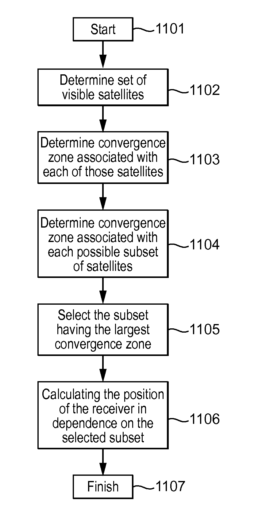
[0052]An apparatus may be arranged to calculate the location of a receiver by means of a location algorithm that generates a receiver location in dependence on signalling events received from a set of satellites. The receiver may be able to receive signalling events from a plurality of satellites, representing the constellation of satellites that are visible to the receiver or a part thereof. The apparatus is preferably arranged to perform the calculation in such a way as to extend a convergence zone within which the algorithm is capable of generating the correct location for the receiver, despite an error in estimates of receiver location and absolute time that are used in the calculation.

[0053]One or more embodiments of the invention may be implemented in a satellite navigation or GNSS system, such as GPS, Globalnaya Navigatsionnaya Sputnikovaya Sistema (GLONASS), Galileo, etc. Therefore, while one or more embodiments of the invention are described below specifically in reference ...


PUM


Abstract

Apparatus for calculating the location of a receiver in a satellite navigation system, the apparatus being arranged to calculate a location of the receiver by means of an algorithm that utilises an estimate of receiver location and / or an estimate of absolute time, the apparatus being arranged to perform the calculation in such a way as to extend a convergence zone within which the algorithm is capable of generating the correct location for the receiver despite an error in the estimate(s).

Description

BACKGROUND OF THE INVENTION[0001]The invention relates to an apparatus and a method for locating a Global Navigation Satellite System (GNSS) receiver.[0002]The Global Positioning System (GPS) is an example of a GNSS navigation system in which a receiver determines its position by precisely measuring the arrival time of signalling events received from multiple satellites. Each satellite transmits a navigation message containing the precise time when the message was transmitted and ephemeris information. For the GPS system, the navigation message may be organised in super-frames, frames, sub-frames, and words of 30 bits each. Each sub-frame of the navigation message starts with a telemetry word (TLM) and the number of the sub-frame. The start of the sub-frame may be detected by means of a preamble sequence in the TLM. Each sub-frame also includes a handover word (HOW) which gives the exact time of the week (TOW) when the satellite will transmit the next sub-frame according to the loca...

Claims


Application Information

Patent Timeline
Patent Type & Authority Applications(United States)
IPC IPC(8): G01S19/42
CPCG01S19/25G01S19/42G01S19/28
Inventor PRATT, ANTHONY RICHARDJARVIS, MURRAY ROBERT
Owner QUALCOMM TECH INT
Why Eureka
Try Eureka