Lamp Unit

Active Publication Date: 2013-01-24
PANASONIC CORP
View PDF8 Cites 4 Cited by
  • Summary
  • Abstract
  • Description
  • Claims
  • Application Information

AI Technical Summary

Benefits of technology

[0007]In such a situation, when removing the lamp unit from the projector, a worker holds a handle section of the lamp unit and pulls out the lamp unit. Then, the lamp unit removed from the projector is placed down on an arbitrarily location by the worker. However, with a hitherto known lamp unit, there has not been any consideration regarding the stability of the lamp unit when it is placed down on a surface after being removed, and the lamp unit may topple backward. If the lamp unit topples backward, the outer circumferential surface of the lamp in the high temperature state makes contact with a placement surface (e.g., surface of

Problems solved by technology

However, if the lamp breaks or if the illumination intensity of the lamp rapidly decreases while the projector is in use, there is a need to replace the lamp unit immediately; thus, the lamp unit has to be replaced while the lamp is still in

Method used


Image

  • Lamp Unit
  • Lamp Unit
  • Lamp Unit

Examples


first embodiment

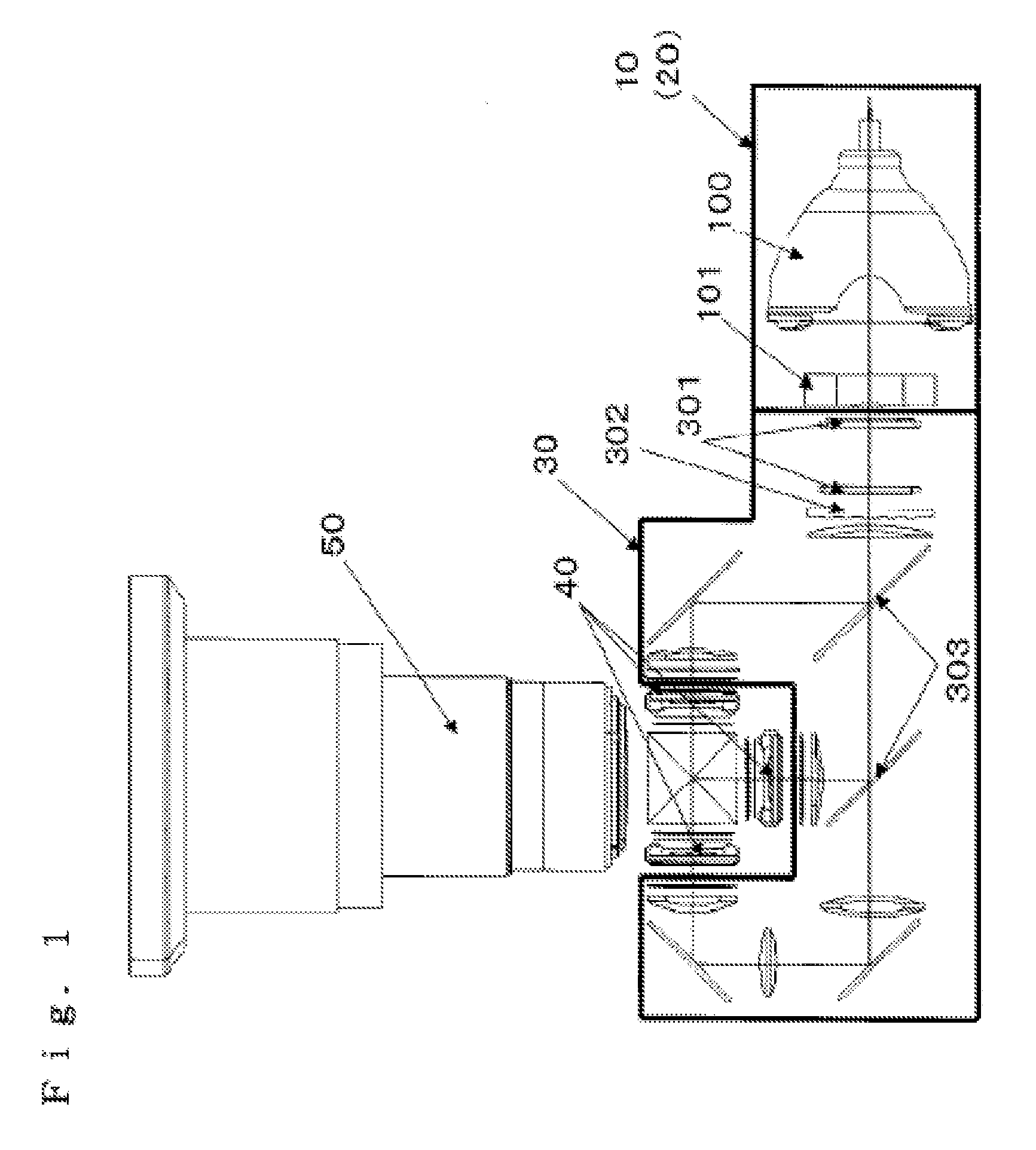
[0030]FIG. 1 is a schematic diagram showing a configuration of a projector.

[0031]A projector includes: a lamp unit 10 having a lamp 100 (e.g., mercury lamp), etc.; an illumination optical system 30 configured to cause light from the lamp 100 serving as a light source to become parallel beams; an image displaying system configured to modulate the parallel beams from the illumination optical system 30 in accordance with image information and generate image projection light; and a projection optical system configured to project the image projection light onto a screen. In the illumination optical system 30, light projected from the lamp unit 10 is caused to become parallel light by a lens array 301, converted into unidirectional linear polarized light by a polarization conversion element 302, and separated into 3 colors of RGB by a dichroic mirror 303. The image displaying system includes an image formation device 40 that modulates each color of light separated by the illumination opti...

second embodiment

[0042]Since components included in a projector in a second embodiment are same as the components in the first embodiment, detailed descriptions thereof are omitted.

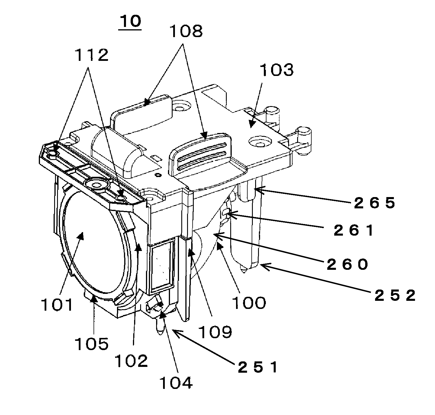
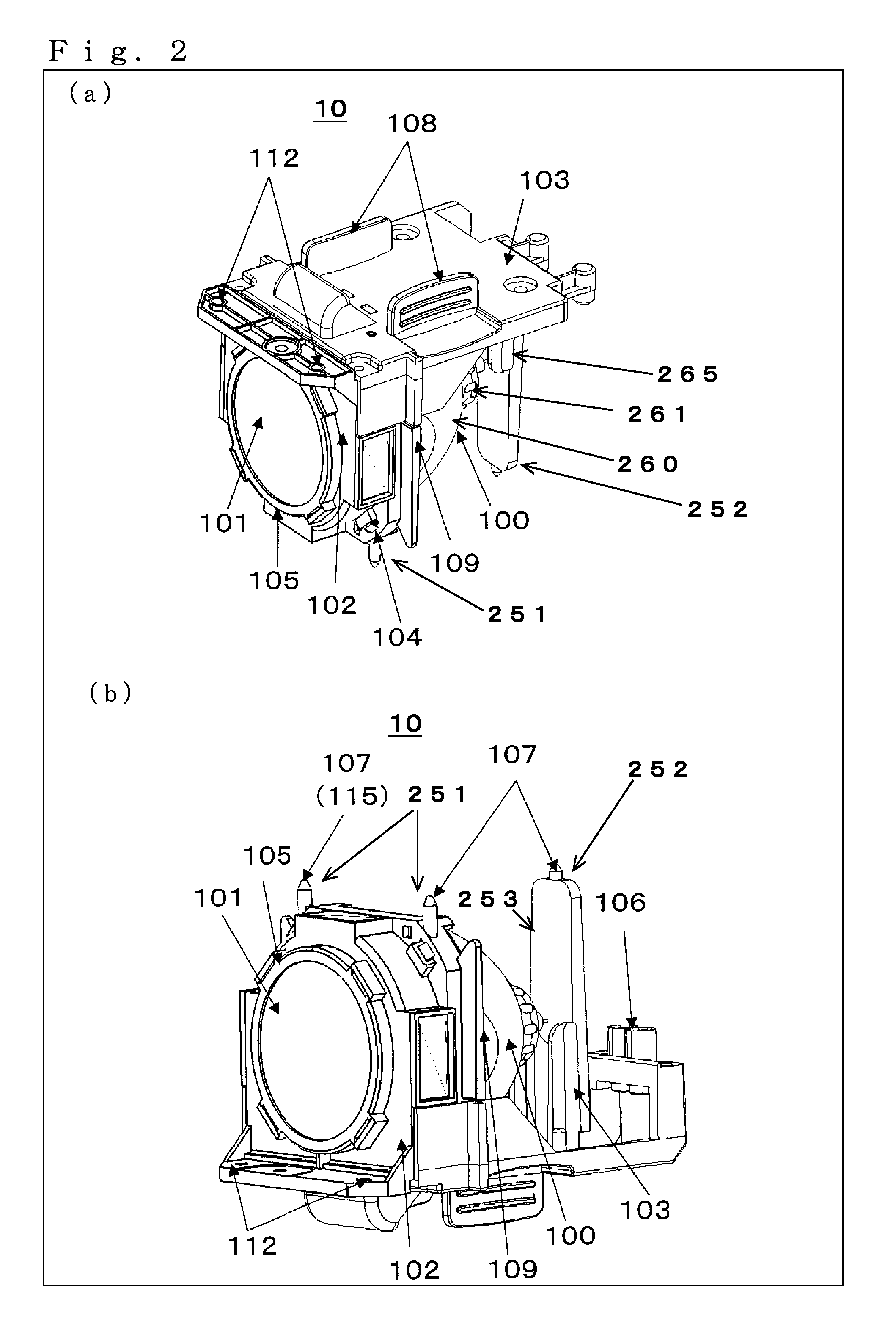
[0043]FIG. 4 is a schematic structural diagram of the lamp unit 10 according to the second embodiment. (a) of the same figure is a perspective diagram viewing the lamp unit 10 from the handle section 108 side, and (b) of the same figure is an upside down perspective diagram of that of (a) of the same figure. FIG. 5 is a schematic structural diagram regarding installation of the lamp unit 10 according to the second embodiment. (a) of the same figure is a perspective diagram viewing the lamp housing 300 from above, and (b) of the same figure is an inner perspective diagram of the lamp housing 300 when the lamp unit 10 is taken out. The projector is structured so that the lamp unit 10 and the illumination optical system 30 can be separated. When the lifespan of the lamp 100 elapses, the worker can open the lamp lid (diagramm...

third embodiment

[0049]Since components included in a projector in a third embodiment are same as the components in the first embodiment, detailed descriptions thereof are omitted.

[0050]FIG. 6 is a schematic structural diagram of the lamp unit 10 according to the third embodiment. (a) of the same figure is a perspective diagram viewing the lamp unit 10 from the handle section 108 side, and (b) of the same figure is an upside down perspective diagram of that of (a) of the same figure. FIG. 7 is a schematic structural diagram regarding installation of the lamp unit 10 according to the third embodiment. (a) of the same figure is a perspective diagram viewing the lamp housing 300 from above, and (b) of the same figure is an inner perspective diagram of the lamp housing 300 when the lamp unit is taken out. The projector is structured so that the lamp unit 10 and the illumination optical system 30 can be separated. When the lifespan of the lamp 100 elapses, the worker can open the lamp lid (diagrammatic r...


PUM


Abstract

A lamp unit 10 includes a lamp 100, a lamp holder 102/103 for holding the lamp 100, a handle section 108 used when removing the lamp unit 10 from a projector, and a support section 251/252 for supporting the lamp unit 10 from below. The support section 251/252 includes a front side support section 251 for supporting the lamp unit 10 at a front side of the lamp unit 10, and a back side support section 252 that is disposed behind the lamp 100 and is for supporting the lamp unit 10 at a tip thereof located outside an outer circumference of the lamp 100 when the lamp unit 10 is viewed from front.

Description

BACKGROUND OF THE INVENTION[0001]1. Field of the Invention[0002]The present invention relates to a lamp unit that functions as a light source of a projector, and, in particular, relates to a lamp unit detachably included in a projector.[0003]2. Description of the Background Art[0004]Lamp units that are detachably included in projectors have been hitherto known. For example, a projector includes: a lamp unit having a light source section; an illumination optical system configured to cause light emitted from the lamp unit to be parallel; an image displaying system configured to modulate parallel beams in accordance with image information and generate image projection light; and a projection optical system having a projection lens for projecting the image projection light onto a screen.[0005]A lamp is used in the light source section. It is necessary to replace the lamp after a certain amount of time, since the brightness of the lamp deteriorates in accordance with the time it has been...

Claims


Application Information

Patent Timeline
IPC IPC(8): F21V21/08
CPCG03B21/145G03B21/2046G03B21/20
Inventor SARUWATARI, NAOTOGOTOU, MASANORISEKIDO, HIROSHIHOSHINO, MAKOTO
Owner PANASONIC CORP
Why Eureka
Try Eureka