Battery device and battery device module

a battery device and module technology, applied in the direction of cell components, electrical appliances, cell temperature control, etc., can solve the problems of low heat dissipation efficiency, limited improvement of heat dissipation effect, failure of battery device performance, etc., to increase the thickness of the battery device, reduce the effect of heat dissipation structur

Inactive Publication Date: 2013-01-24
DELTA ELECTRONICS INC
View PDF0 Cites 14 Cited by
  • Summary
  • Abstract
  • Description
  • Claims
  • Application Information

AI Technical Summary

Benefits of technology

[0009]An objective of the present invention is to provide a battery device and a battery device module which are provided with a heat dissipating structure. The heat dissipating structure allows for liquid to flow therethrough to carry the heat away from the battery device quickly, but does not significantly increase the thickness of the battery device.

Problems solved by technology

However, battery devices generate heat when outputting the electric power, and if the heat is not effectively dissipated, it will accumulate in the battery device and possibly cause failure in the performance of the battery device.
However, the convection between the heat dissipating fins and the ambient air only provides a low heat dissipation efficiency, and even when fans are additionally provided near the heat dissipating fins to blow air towards the heat dissipating fins, improvement to the heat dissipation effect is still limited and, on the other hand, both the cost and the space occupation of the battery device will be increased.
However, although the water-cooling plate can dissipate heat quickly, the geometry thereof causes the thickness of the battery device to become significantly larger.

Method used


Image

  • Battery device and battery device module
  • Battery device and battery device module
  • Battery device and battery device module

Examples


first embodiment

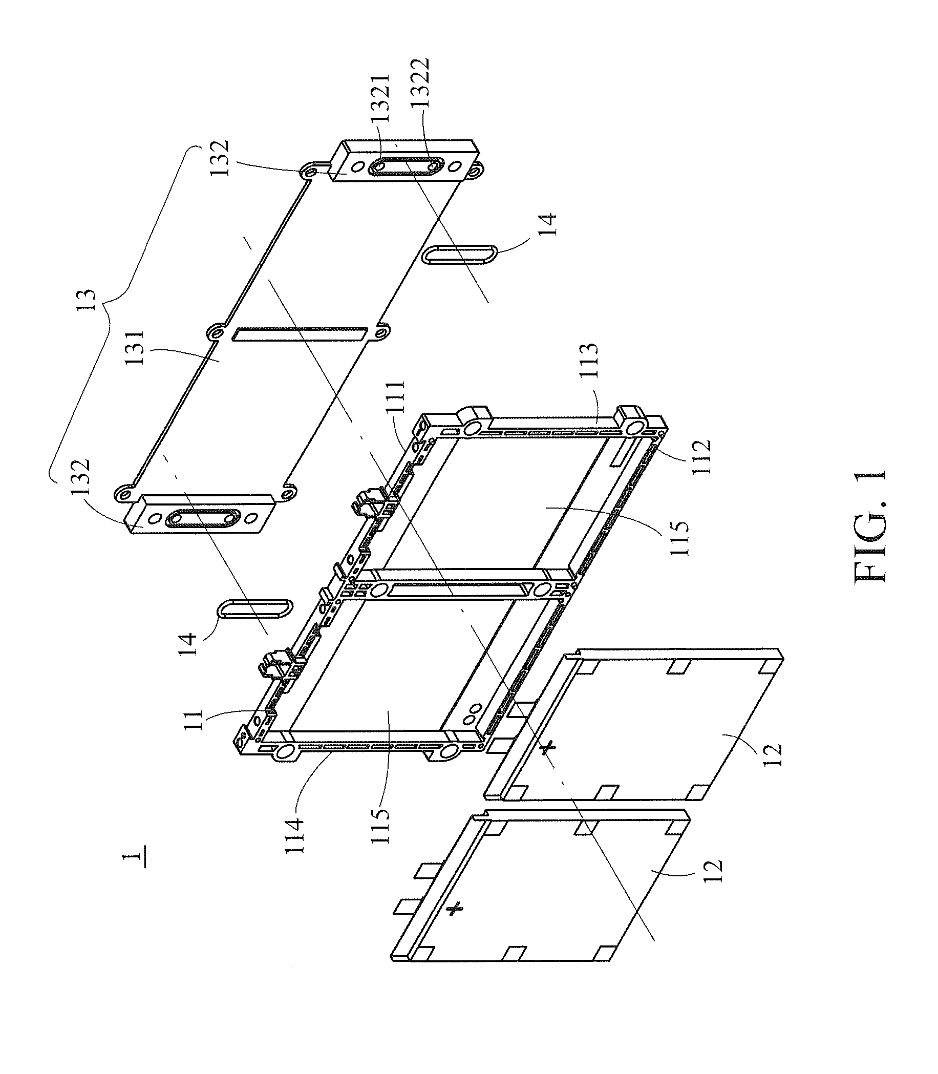
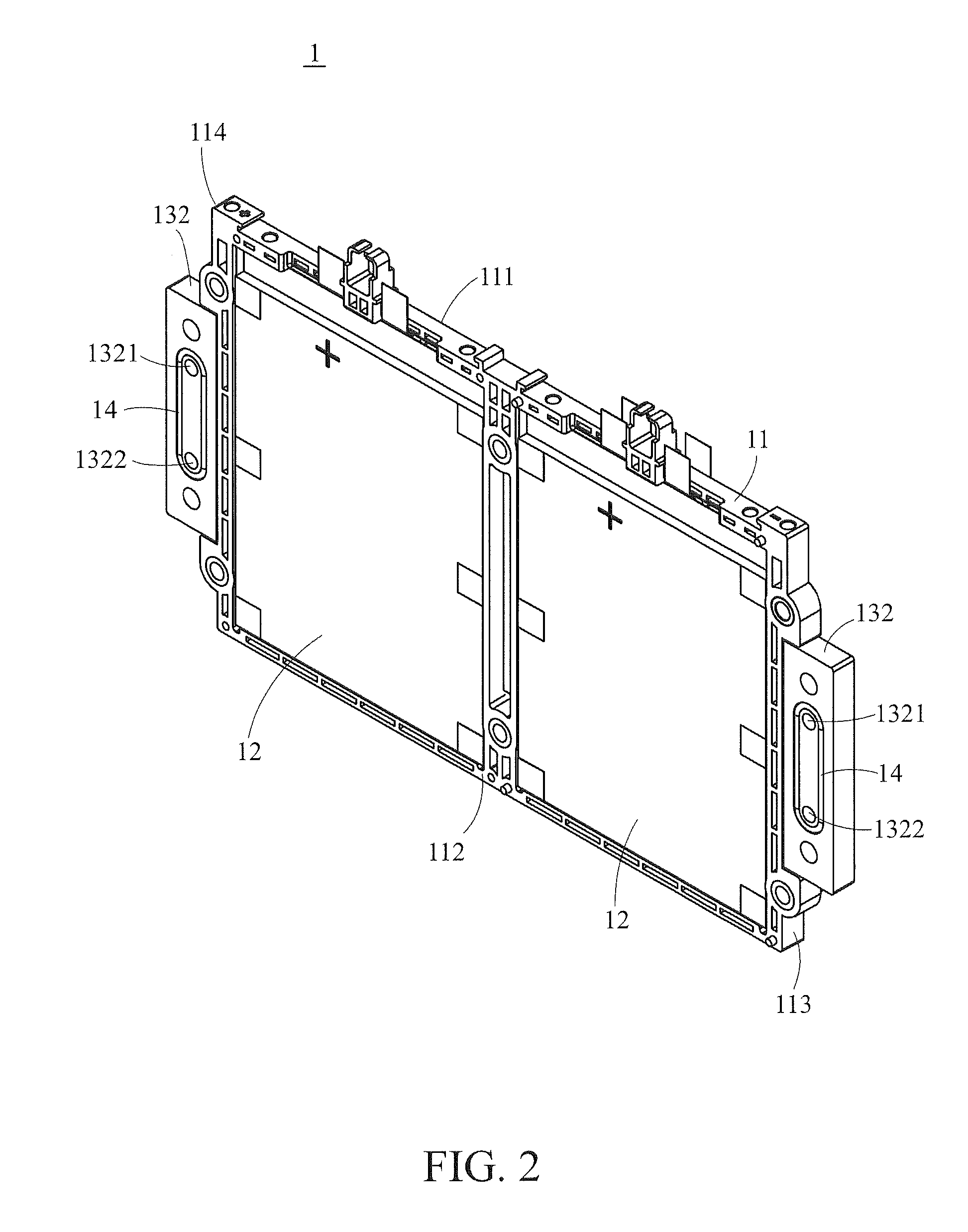
[0028]Referring to FIGS. 1 to 3, a perspective exploded view, a perspective assembly view and a side view of a battery device 1 according to the present invention are shown therein respectively. The battery device 1 comprises a fixing frame 11, at least one battery 12, a heat dissipating structure 13 and two seal rings 14. Hereinbelow, these components will be described in sequence.

[0029]The fixing frame 11 is adapted to support and fix the battery 12. The fixing frame 11 is substantially of a rectangular plate form, and may have a first plane 111, a second plane 112, a third plane 113 and a fourth plane 114. The first plane 111 is set apart from the second plane 112, while the third plane 113 is set apart from the fourth plane 114. The third plane 113 connects to the first plane 111 and the second plane 112. The fourth plane 114 connects to the first plane 111 and the second plane 112 too.

[0030]In this embodiment, the first plane 111, the second plane 112, the third plane 113 and t...

second embodiment

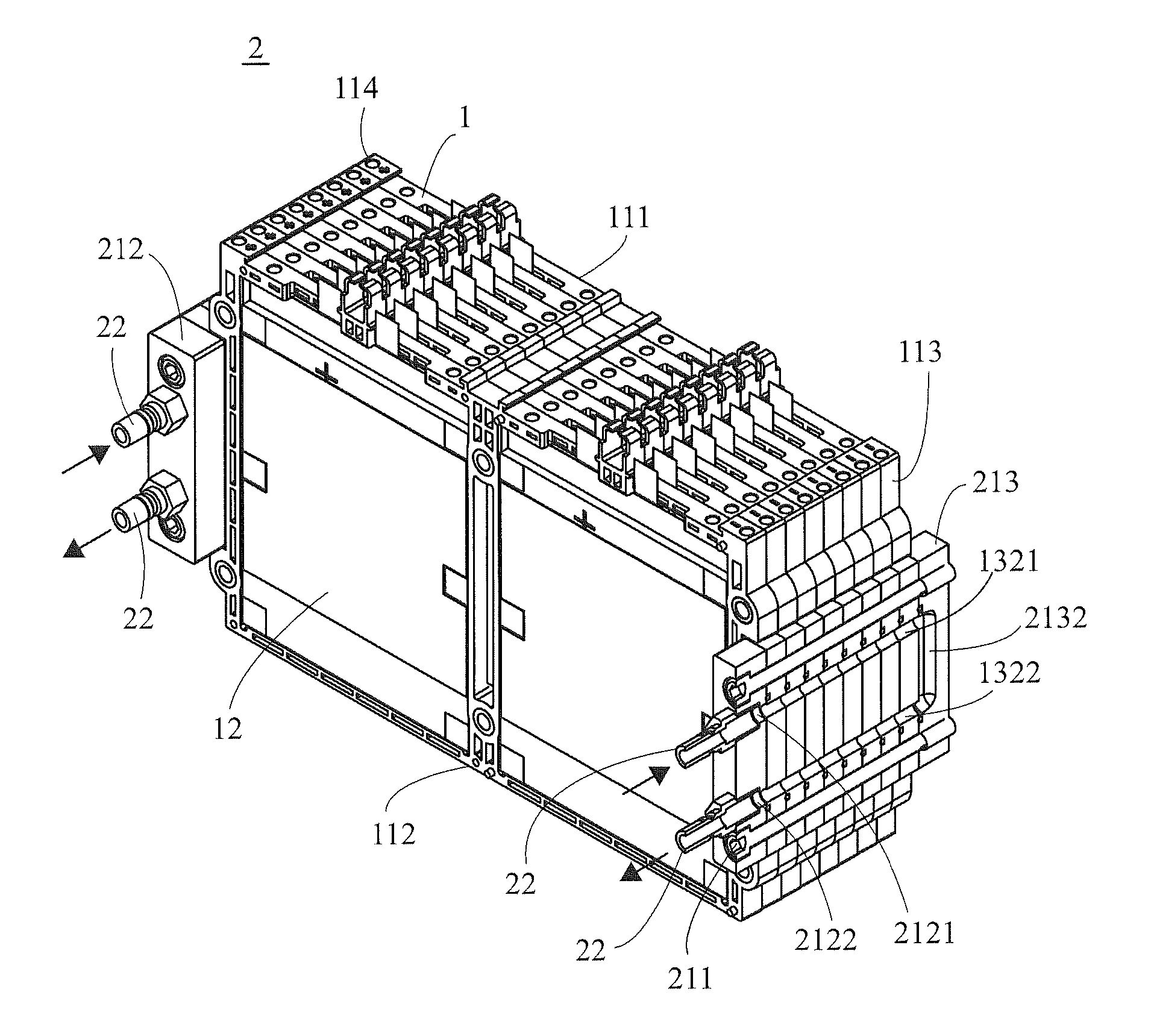
[0055]The fixing device 31 differs from the fixing device 21 of the second embodiment in that, in addition to the plurality of screws 311, first pressing blocks 312 and second pressing blocks 313, the fixing device 31 further comprises a first pressing plate 314 and a second pressing plate 315. The stacked battery devices 1′ are clamped between the first pressing plate 314 and the second pressing plate 315. Additionally, apart from passing through the heat dissipating structures 13′, the screws 311 further pass through the fixing frames 11′ and connect the first pressing plate 314 with the second pressing plate 315.

[0056]By increasing the feeding quantity of the screws 311, the distance between the first pressing plate 314 and the second pressing plate 315 can be shortened so that the battery devices 1′ are clamped tightly into a close stack by the first pressing plate 314 and the second pressing plate 315.

[0057]Referring to FIGS. 9 to 11, two perspective exploded views and a perspe...

fourth embodiment

[0060]Referring to both FIGS. 12 and 13, a perspective assembly view and a partially enlarged view of the battery device 4 according to the present invention are shown therein respectively. The liquid channel 4311b has an input opening 4311d and an output opening 4311e for the liquid to flow into or out of the liquid channel 4311b. The input opening 4311d is disposed in the second input hole 4313 while the output opening 4311e is disposed in the second output hole 4314 so that the first input hole 4321 communicates with the input opening 4311d and the first output hole 4322 communicates with the output opening 4311e.

[0061]Thus, the liquid can flow from the first input hole 4321 to the second input hole 4313, and then through the input opening 4311d into the liquid channel 4311b. The liquid flows along the liquid channel 4311b and then flows out of the output opening 4311e into the second output hole 4314 and the first output hole 4322.

[0062]It is noting that the liquid channel 4311...


PUM

PropertyMeasurementUnit
thicknessaaaaaaaaaa
heataaaaaaaaaa
clamping forceaaaaaaaaaa

Abstract

A battery device is provided, which includes a fixing frame, a battery and a heat dissipating structure. The fixing frame includes a first plane, a second plane and a third plane. The first plane stands apart from the second plane, and the third plane connects the first plane and second plane. A receiving space is formed between the first and the second planes. The battery is disposed in the receiving space. The heat dissipating structure includes a plate and a block connected to the plate. The plate is disposed on the second plane and comes into contact with the battery. The block is disposed on the third plane and has an input hole and an output hole for liquid to pass therethrough. With this arrangement, the heat dissipating structure can quickly dissipate heat from the battery by the liquid flow. A battery device module is also provided in this disclosure.

Description

CROSS-REFERENCES TO RELATED APPLICATIONS[0001]This application claims the benefit of the priority to Taiwan Patent Application No. 100125301 filed on Jul. 18, 2011, the disclosures of which are incorporated herein by reference in their entirety.BACKGROUND OF THE INVENTION[0002]1. Field of the Invention[0003]The present invention relates to a battery device and a battery device module, both of which have a water-cooling heat dissipating structure.[0004]2. Descriptions of the Related Art[0005]Many electronic products must be powered by a battery device to operate. However, battery devices generate heat when outputting the electric power, and if the heat is not effectively dissipated, it will accumulate in the battery device and possibly cause failure in the performance of the battery device. Therefore, effective heat dissipation is very important for the operation and service life of the battery device.[0006]Most conventional practices of solving the problem of heat dissipation in a b...

Claims


Application Information

Patent Timeline
Patent Type & Authority Applications(United States)
IPC IPC(8): H01M10/50H01M50/209H01M50/224H01M50/233H01M50/264H01M50/291
CPCH01M2/1061H01M2/1077H01M10/0481H01M10/5075H01M10/5032H01M10/5055H01M10/5059H01M10/5004H01M10/647H01M10/6557H01M10/6567H01M10/6555H01M10/613Y02E60/10H01M50/224H01M50/233H01M50/264H01M50/291
Inventor HSIAO, YUAN-KUNPAN, PO-LIN
Owner DELTA ELECTRONICS INC
Why Eureka
Try Eureka