
Energy storing device and method of using the same

a technology of energy storage and energy storage device, which is applied in the field of soccer ball having a generation module, can solve the problems of dire environmental, health and economic consequences, households without reliable electricity, and noxious fumes from burning kerosene, and achieve the effects of reducing the risk of lung cancer, and reducing the number of patients

Active Publication Date: 2013-01-24
UNCHARTED POWER INC
View PDF17 Cites 71 Cited by
  • Summary
  • Abstract
  • Description
  • Claims
  • Application Information

AI Technical Summary

Benefits of technology

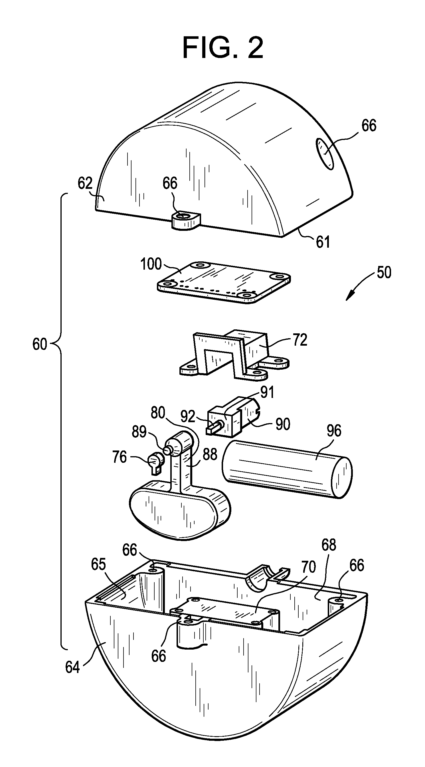
The present invention is about a new kind of ball that has a generation module inside it. This module contains a pendulum and an electric generator. When the ball is moved, the pendulum swings and the electric generator converts the swinging into electrical energy which is then stored in a battery. The battery can be connected to an external socket. The generation module is fixed inside the ball and the pendulum is supported at its center of rotation by two supports. The pendulum is designed to rotate about a specific axis and the electric generator is designed to rotate with the pendulum. This design results in a highly efficient energy conversion system.

Problems solved by technology

This “energy poverty” is a serious problem that has dire environmental, health, and economic consequences, especially for families in the developing world.
With few other alternatives, households without reliable access to electricity often depend on pollutant kerosene lamps to provide extra hours of light after the sun goes down.
The noxious fumes from the burning kerosene are bad for the environment and for respiratory health: just one night of exposure to the kerosene smoke is equivalent to smoking two packs of cigarettes.
Furthermore, kerosene is expensive: a family can spend up to 30% of their income on kerosene each year.
With respect to both lighting and technological access, the lack of readily available electricity is a significant problem.

Method used


Image

  • Energy storing device and method of using the same
  • Energy storing device and method of using the same
  • Energy storing device and method of using the same

Examples


Embodiment Construction

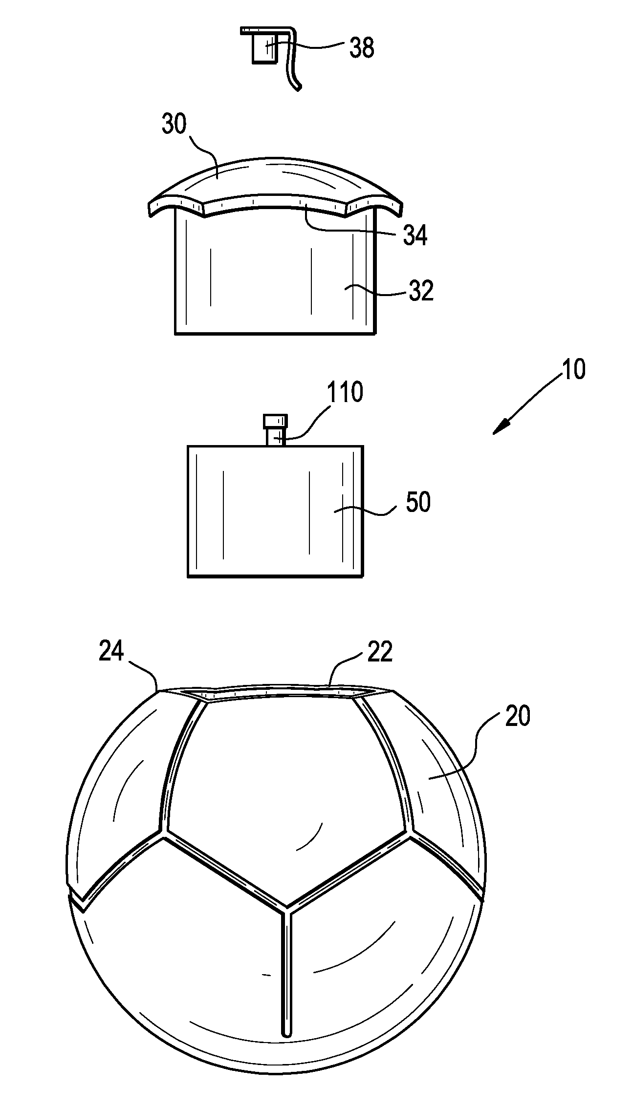
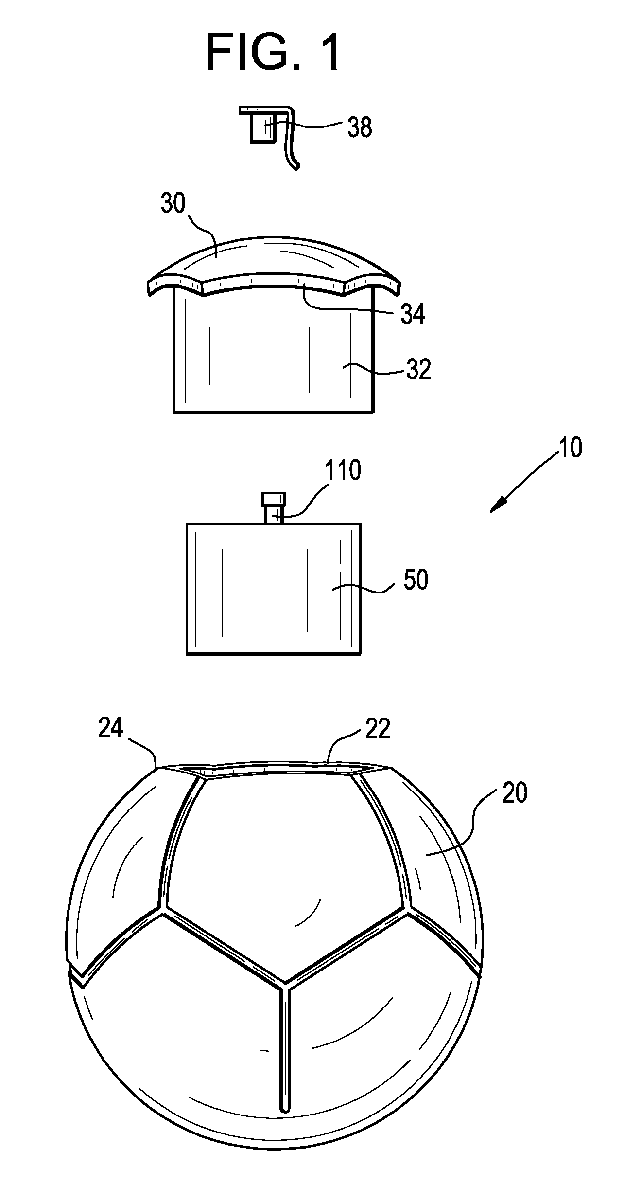
[0023]In reference to the FIGS. generally and with specific reference to FIG. 1, a ball 10 in accordance with one embodiment of the present invention is shown. The ball 10 includes a generally spherical shell 20 that defines a cavity 22. The ball 10 includes a generation module 50 that harnesses kinetic energy of the ball 10 to generate and store electrical energy. The shell 20 defines an opening 24 for accessing the cavity 22 and includes a panel 30 for substantially closing the opening 24 defined by the shell 20. The panel 30 includes a cylindrical sleeve 32 that extends radially inward from an inner surface 34 of the panel 30. During assembly the generation module 50 is secured in the sleeve 32 and the panel 30 is secured in the opening 24 defined by the shell 20 so that the sleeve 32 is disposed in the cavity 22. A socket 110 is electrically coupled to the generation module 50 and is accessible through an opening (not shown in FIG. 1) defined by the panel 30. A cap 38 closes the...


PUM


Abstract

A ball includes a shell defining a spheroid. The shell includes an opening and a panel to close the opening. The panel has a sleeve that extends radially inward. A generation module is disposed in a cavity defined by the shell. The generation module includes a housing. A pendulum, an electric generator, and a battery are disposed in the housing. The pendulum is mechanically coupled to a rotor of the electric generator at a first axis of rotation of the pendulum and the electric generator is electrically coupled to the battery. An acceleration of the ball causes the pendulum to rotate about the first axis of rotation. The rotation of the pendulum rotates the rotor of the electric generator. The rotation of the rotor of the electric generator generates electricity, and at least a portion of the generated electricity is stored by the battery.

Description

CROSS REFERENCE TO RELATED APPLICATIONS[0001]This application is a continuation-in-part of U.S. patent application Ser. No. 12 / 592,991 filed Dec. 7, 2009.[0002]This application claims the benefit of U.S. Provisional Patent Application No. 61 / 521,826 filed on Aug. 10, 2011, the contents of which are incorporated herein by reference in their entirety.FIELD OF THE INVENTION[0003]The present invention relates to a ball having a generation module disposed therein. More specifically, the present invention relates to a soccer ball having a generation module disposed in a cavity of the ball, wherein the generation module generates electrical energy from the balls kinetic energy and stores that electrical energy.BACKGROUND OF THE INVENTION[0004]The total number of individuals in the World without electric power is put at about 1.5 billion, or a quarter of the world's population, concentrated mostly in Africa and southern Asia. See Nathanial Gronewold, One-Quarter of World's Population Lacks ...

Claims


Application Information

Patent Timeline
Patent Type & Authority Applications(United States)
IPC IPC(8): A63B43/00
CPCA63B43/00A63B43/06A63B2220/53A63B2220/12A63B2220/833F03G7/08A63B43/04A63B2220/58F03G5/06F03G5/066
Inventor IDONI-MATTHEWS, JESSICA O.SILVERMAN, JULIA CLAIREMOSTI, VICTOR ANGELMANALO, JOEL
Owner UNCHARTED POWER INC
Learn More