Snap faster

a fastener and snap technology, applied in the field of snap fasteners, can solve the problems of unintended loosening of the snap fastener in the slide-shaped prior art, difficult simultaneous positioning of the snap fastener, and simplification over the prior art, and achieve the effect of reducing pressure and accurately fastening to on

Inactive Publication Date: 2013-01-31
RAMSAUER DIETER
View PDF12 Cites 1 Cited by
  • Summary
  • Abstract
  • Description
  • Claims
  • Application Information

AI Technical Summary

Benefits of technology

[0011]By means of this step, for example, the quantity of structural component parts required for the fastener according to the invention is reduced because only one lever is required instead of two push elements. In the prior art, two holding elements carry out opposed translational linear movements against spring force or with the support of spring force, respectively, during the fastening process and unlocking process. Accordingly, unlocking by means of a key requires that the rotational movement of the key be transformed into translational movement of the holding elements, which increases the force required for unlocking because of jamming occurring between the slide-shaped holding element and the guide thereof In contrast, the rotational movement of the lever which forms or carries the two holding elements at its ends takes place without the occurrence of jamming. Further, with high vibration loading, jamming processes of this kind can lead to an unintended loosening of the snap fastener in the slide-shaped prior art, which does not occur in the lever-shaped design according to the invention. A further development of the invention is characterized in that a spring, such as a coil spring, extending around the shaft is provided for generating the spring force, one end of which spring is fixed in an aperture arranged in the vicinity of the shaft, while the other end is fixed in the housing supporting the shaft. This also results in a simplification over the prior art which requires two coil springs.
[0013]The problem can be solved, according to the invention, in that a compression spring, particularly a coil spring or a concave leaf spring such as a spring washer, is arranged between the support surface of the base part and the associated edge plane of the thin wall (front surface). In this way, the snap fastener is automatically pressed into a position that allows one wall to be removed from the other without having to pay close attention to the individual snap fasteners.
[0014]By means of this compression spring such as a spring washer, a greater range of play is also bridged in that play can also be balanced between the compression spring and coil spring. The spring-supported play can also be used with closures in electrical installations to allow the door or shutter to be lifted up to permit occurring gases to escape or to relieve pressure. It is also possible for panels of different thickness to be accurately fastened to one another without changing the snap fastener.
[0016]Further, as a result of the spring washer, the spring protrudes into the snap fastener far enough without the base part projecting out far that it need not be pulled out any farther in order to remove one thin wall from the other thin wall. Further, the spring enlarges the clamping area. This has the additional advantage that it furnishes a means for checking that the walls have been successively connected because, if the hold should fail, this spring pushes the snap fastener back out again, thereby showing that it has not engaged.

Problems solved by technology

Further, with high vibration loading, jamming processes of this kind can lead to an unintended loosening of the snap fastener in the slide-shaped prior art, which does not occur in the lever-shaped design according to the invention.
This also results in a simplification over the prior art which requires two coil springs.
The prior art has the further disadvantage that when fastening one wall part to another wall part with a plurality of snap fasteners of the type mentioned above it can be very difficult to simultaneously position the snap fasteners in such a way as to allow one wall part to be removed from the other wall part.

Method used


Image

  • Snap faster
  • Snap faster
  • Snap faster

Examples


Embodiment Construction

[0030]It is to be understood that the figures and descriptions of the present invention have been simplified to illustrate elements that are relevant for a clear understanding of the present invention, while eliminating, for purposes of clarity, many other elements which are conventional in this art. Those of ordinary skill in the art will recognize that other elements are desirable for implementing the present invention. However, because such elements are well known in the art, and because they do not facilitate a better understanding of the present invention, a discussion of such elements is not provided herein.

[0031]The present invention will now be described in detail on the basis of exemplary embodiments.

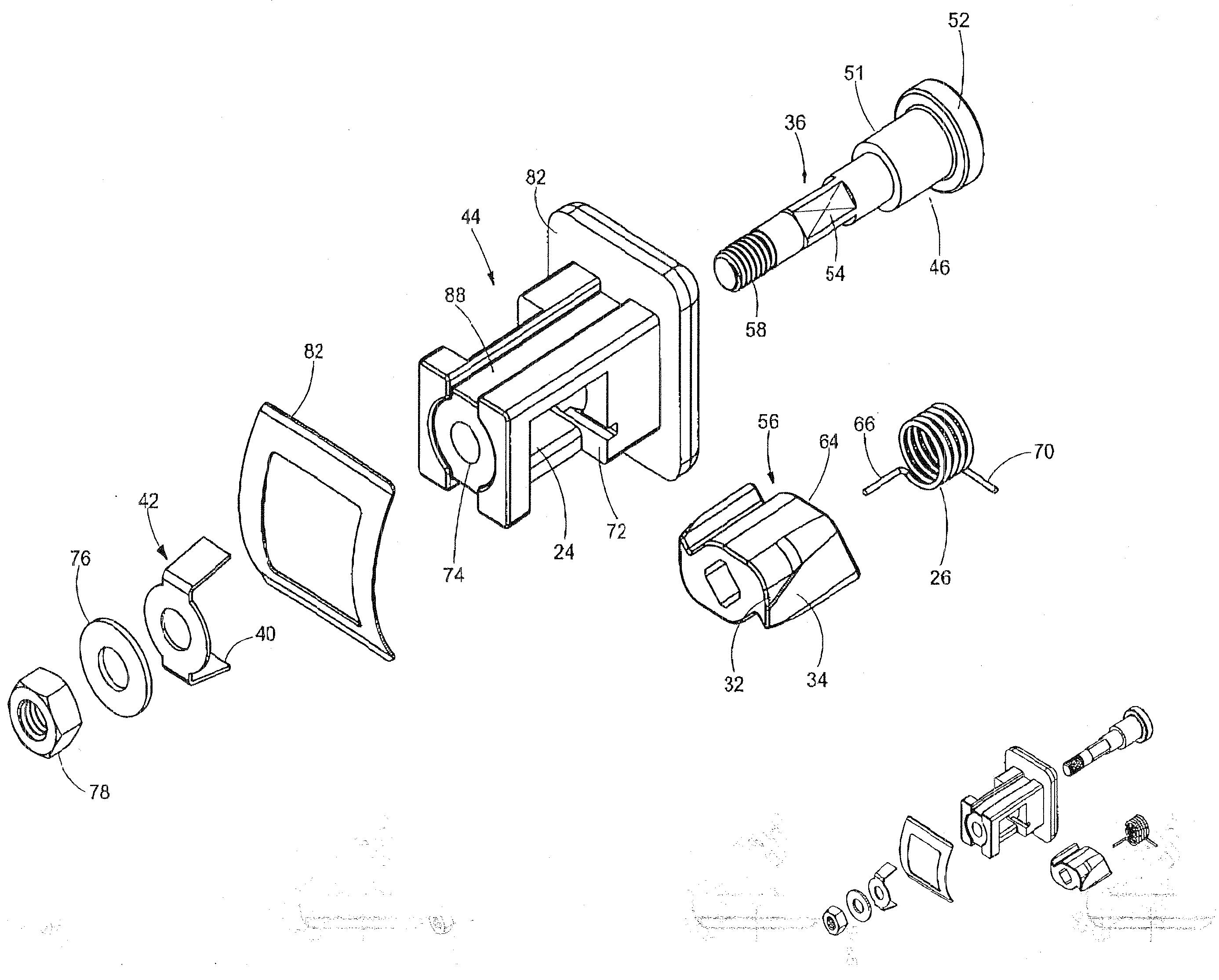
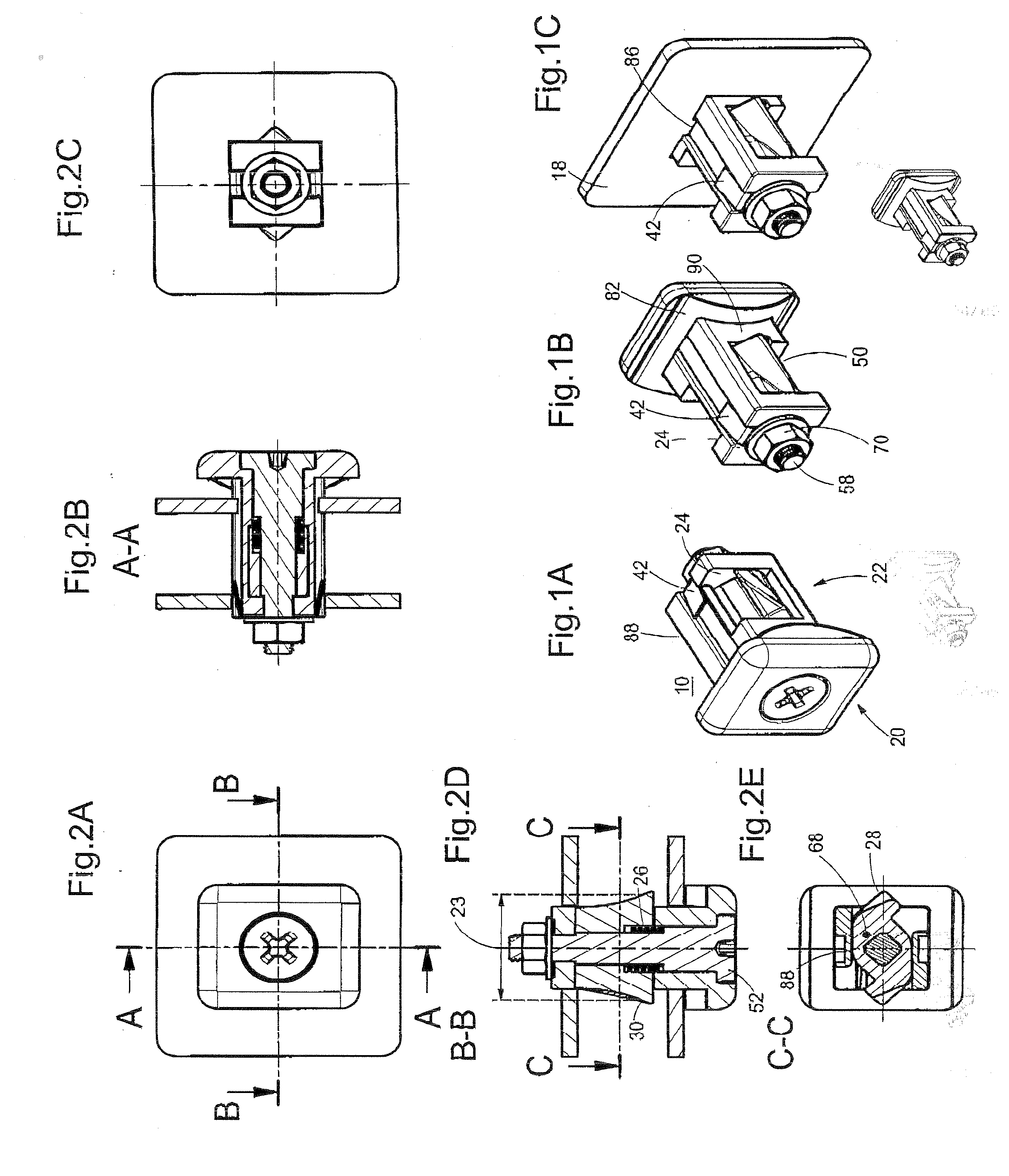
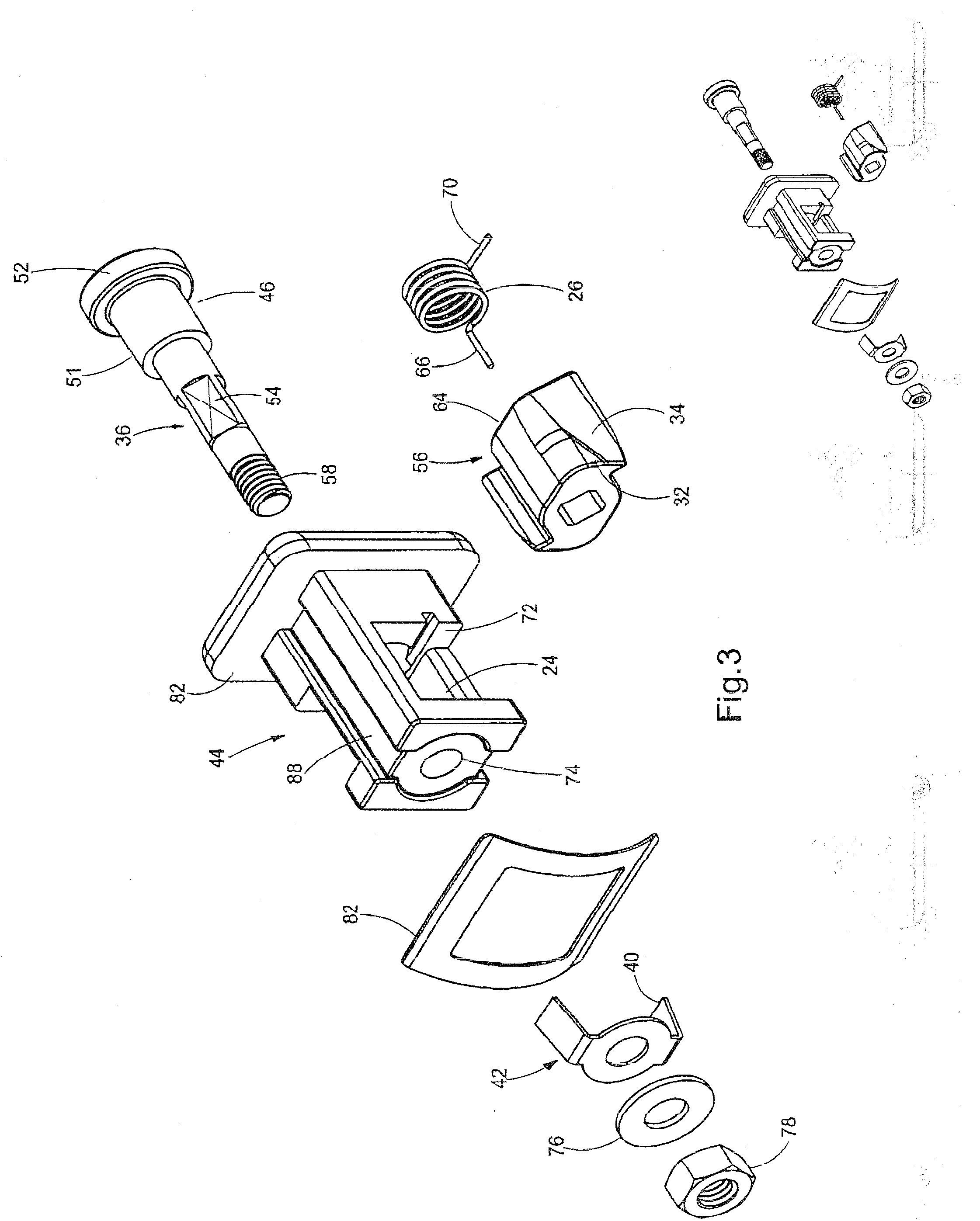
[0032]FIG. 1A shows a snap fastener 10 suitable for fastening a first thin wall 18 such as a housing wall, door leaf, shutter, or the like, which is provided with a through-opening 16 to a second thin wall 14 such as a thin-walled wall support such as a housing frame, door fram...


PUM


Abstract

Snap fastener for fastening a first thin wall to a second thin wall, having a base part to be arranged in a through-opening of the first thin wall. A head part extends away from the base part. The head part presents a guide for two holding elements which are pressed by a spring so that they project out over the end of the guide. The head part includes a housing with fastening projections, and can be snapped into the through-opening so that it grips only one thin wall. Unlocking devices, via which the holding elements can be pulled back into the housing from the front, are provided in the housing. The holding elements are formed by the ends of a two-armed lever which is held on a shaft in the housing so as to be rotatable at an angle of approximately 45 to 90 degrees against spring force.

Description

BACKGROUND OF THE INVENTION[0001]The present application claims priority from PCT Patent Application No. PCT / EP2010 / 006495 filed on Oct. 23, 2010, which claims priority from German Patent Application No. DE 20 2009 016 632.5 filed on Dec. 8, 2009, the disclosures of which are incorporated herein by reference in their entirety.BACKGROUND OF THE INVENTION[0002]1. Field of the Invention[0003]The invention is directed to a snap fastener suitable for fastening a first thin wall such as a housing wall, door leaf, shutter, or the like, which is provided with a through-opening, to a second thin wall such as a thin-walled wall support such as a housing frame, door frame, wall opening edge, or the like, which is likewise provided with a through-opening, having a base part which can be arranged at the first (or second) thin wall in the through-opening thereof, having a head part extending away from this base part, this head part having in its longitudinal section a diameter which initially inc...

Claims


Application Information

Patent Timeline
Patent Type & Authority Applications(United States)
IPC IPC(8): F16B13/10F16B2/20
CPCE05B9/084Y10T24/45257
Inventor RAMSAUER, DIETER
Owner RAMSAUER DIETER
Why Eureka
Try Eureka