Method for building up plasma on an optical fiber preform, while reducing nitrogen oxides

Inactive Publication Date: 2009-12-08
DRAKA COMTEQ BV
View PDF12 Cites 0 Cited by
  • Summary
  • Abstract
  • Description
  • Claims
  • Application Information

AI Technical Summary

Benefits of technology

[0009]Each gaseous reducing element is preferably selected from: hydrogen; ammonia; carbon monoxide; and light hydrocarbons, in particular methane, ethane, propane, and butane. Furthermore, each solid reducing element is preferably selected from: urea, and ammonium fluoride, and derivatives t

Problems solved by technology

Such an installation is expensive both in terms of its own manufacture and installation, and in terms of its running costs.
In addition, that type of installation is relatively bulky.
Furthermore, heating the residual gases by means of natural gas gives rise to a large di

Method used


Image

  • Method for building up plasma on an optical fiber preform, while reducing nitrogen oxides
  • Method for building up plasma on an optical fiber preform, while reducing nitrogen oxides
  • Method for building up plasma on an optical fiber preform, while reducing nitrogen oxides

Examples


first embodiment

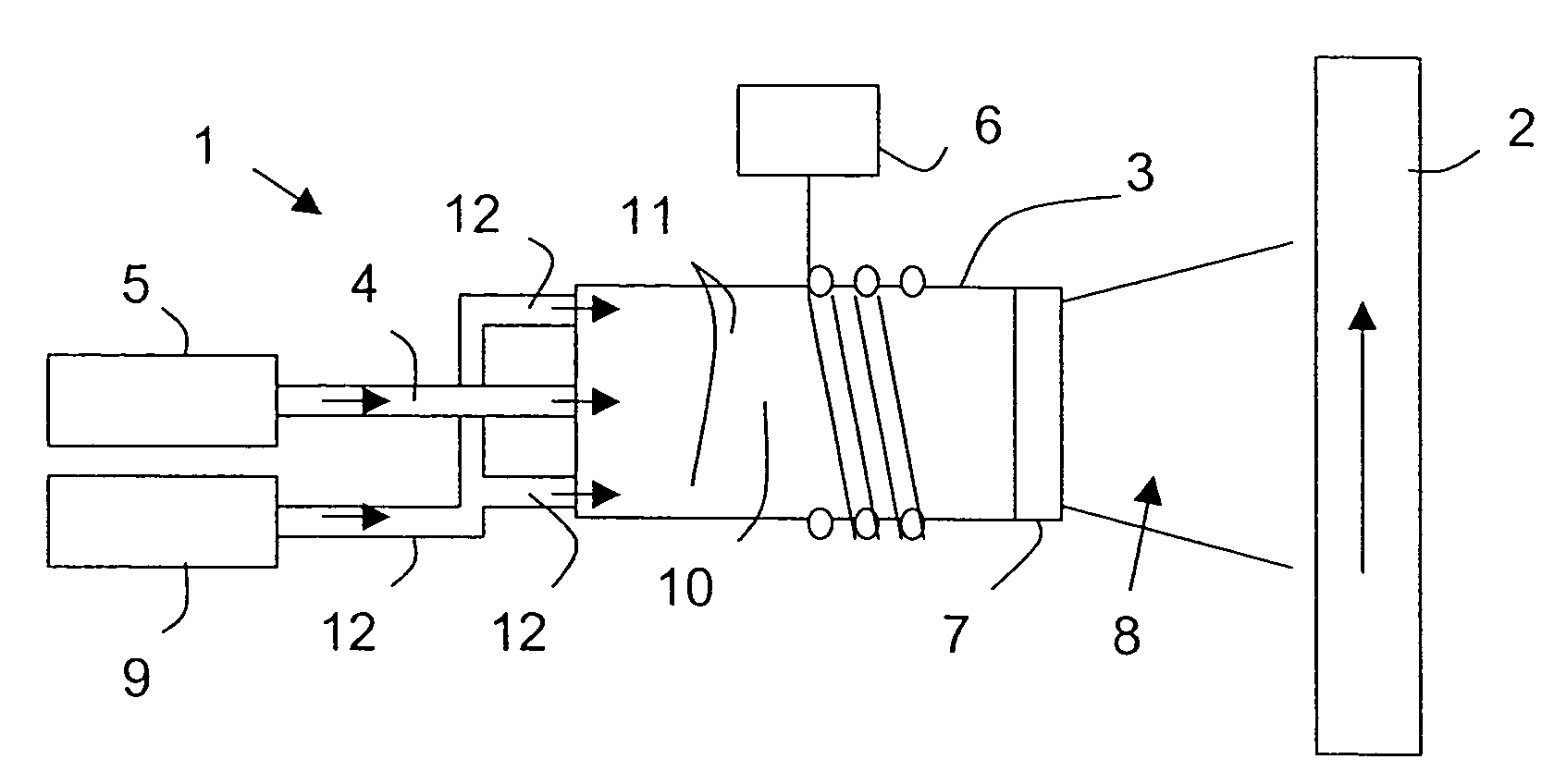
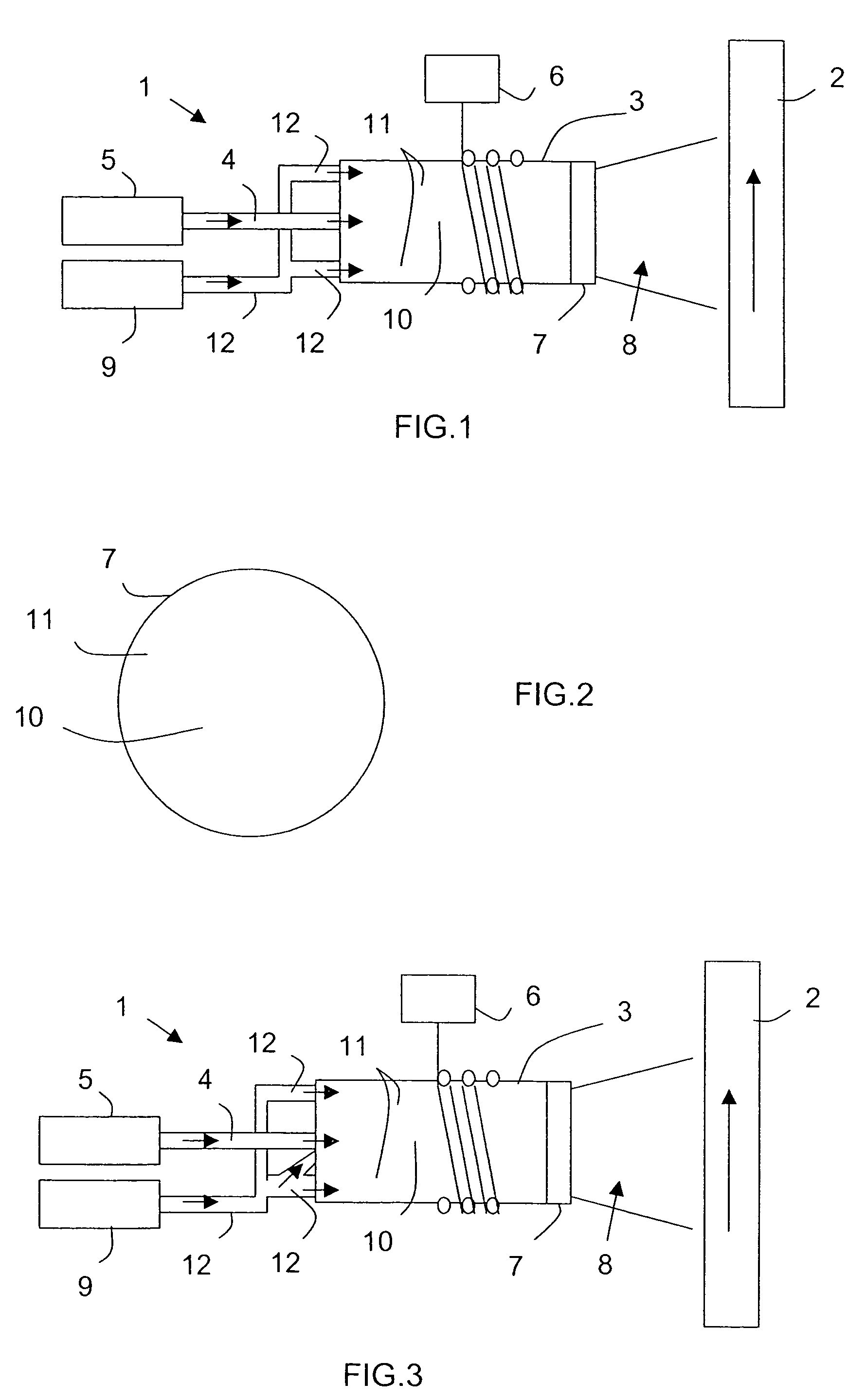
[0030]Reference is made initially to FIGS. 1 and 2 to describe apparatus of the invention.

[0031]The plasma buildup apparatus 1 comprises a plasma torch 3 coupled by a pipe 4 to a feed module 5 for feeding a plasma-generating gas such as oxygen, nitrogen, or argon, or a combination of two of them, and surrounded by a coil fed with high frequency current by a generator 6.

[0032]Usually, the plasma-generating gas injected into the plasma torch 3 is a mixture of nitrogen and oxygen. In addition, although not always shown in the figures, a fraction of the plasma-generating gas is generally introduced into a central portion 10 of the plasma torch, while the remainder is introduced at a different rate into the periphery 11 around the central portion 10. It is important to observe that there is no partition separating the central and peripheral portions 10 and 11.

[0033]A plasma of ionized gas at high temperature is generated inside the plasma torch 3 and is delivered at the end of an outlet ...

second embodiment

[0041]Reference is now made to FIG. 3 to describe apparatus of the invention. This embodiment constitutes a variant of the apparatus described above described with reference to FIGS. 1 and 2.

[0042]In this example, the feed module 9 feeds one or more reducing elements, preferably accompanied by air, via pipes 12, not only to the peripheral zone 11, but also to the central zone 10. In a variant that is not shown, it is also possible to envisage the feed module 9 comprising two independent subportions respectively feeding the central and peripheral zones 10 and 11 of the plasma torch 3 with different reducing elements (preferably accompanied by air).

third embodiment

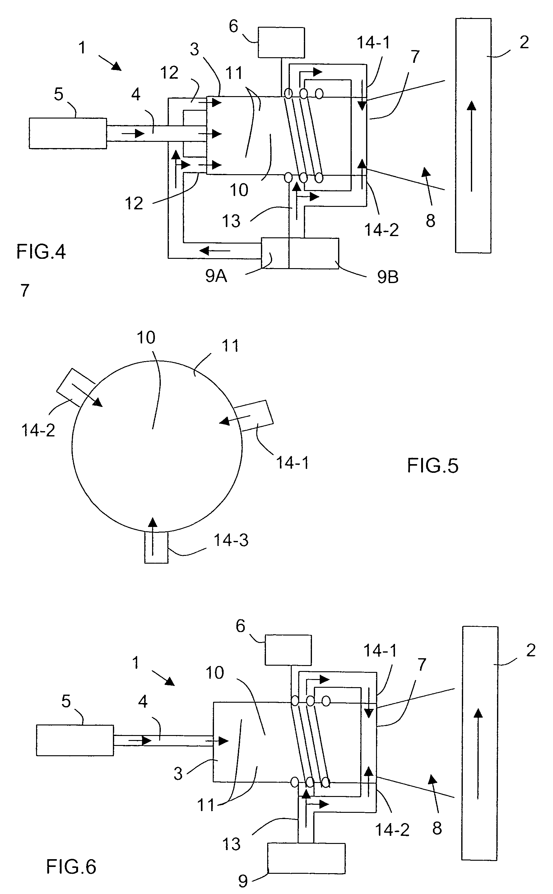
[0043]Reference is now made to FIGS. 4 and 5 while describing apparatus of the invention. This apparatus constitutes a second variant of the apparatus described above with reference to FIGS. 1 and 2.

[0044]In this example, the feed module 9 is subdivided into at least two submodules 9A and 9B which feed preferably different reducing elements not only to the upstream portion of the plasma torch 3 via pipes 12, but also to the downstream portion of the torch at the end of its outlet nozzle 7 via pipes 13. The end of the outlet nozzle 7 has at least one inlet 14 connected to a pipe 13 and arranged to deliver one or more reducing elements to the outlet of the plasma torch 7 at at least one location. For example, the upstream portion of the plasma torch 3 is fed with air and hydrogen by the feed submodule 9A via the pipe 12, while the inlets 14 of the outlet nozzle 7 are fed with ammonia (NH3) by the feed submodule 9B via the pipes 13.

[0045]As shown in FIG. 5, three inlets 14-1 to 14-3 ar...


PUM


Abstract

A plasma buildup method for building up an optical fiber perform. The method includes the steps of: providing a plasma torch having an outlet nozzle adjacent to a primary perform, wherein an interaction zone is defined between the outlet nozzle and the primary preform; feeding the plasma torch with a plasma-generating gas in the presence of a silica-based material so as to deposit a buildup material on the primary preform; and introducing a reducing element into the interaction zone, the reducing element reacting to induce reduction of the nitrogen oxides produced by interaction between nitrogen and oxygen in the presence of the plasma generated by the torch.

Description

BACKGROUND OF THE INVENTION[0001]The invention relates to the field of optical fibers, and more precisely to the fabrication of optical fibers by depositing a buildup material on a preform by means of a plasma torch.[0002]Plasma buildup of a “primary” optical fiber preform is a technique that serves to increase the diameter of the preform considerably, and consequently to enable optical fibers of greater length to be drawn. This technique is described in particular in documents EP 0 401 742, EP 0 450 465, and EP 0 658 520.[0003]Because of the high temperatures generated by the plasma produced by the plasma torch, interaction between the nitrogen and the oxygen contained in the confined enclosure where buildup is performed generates nitrogen oxides (NOx).[0004]These nitrogen oxides are exhausted from the enclosure and collected by a processing installation for restricting rejection to the atmosphere in compliance with antipollution standards. Such processing installations generally m...

Claims


Application Information

Patent Timeline
IPC IPC(8): H05H1/26C03B37/012C03B37/014
CPCC03B37/01426C03B37/01291
Inventor APPRIOU, ANDRETRUCHOT, CHARLESGUINA, SABINE
Owner DRAKA COMTEQ BV
Why Eureka
Try Eureka