Supercapacitors and method for fabricating the same
- Summary
- Abstract
- Description
- Claims
- Application Information
AI Technical Summary
Benefits of technology
Problems solved by technology
Method used
Image
Examples
example 1
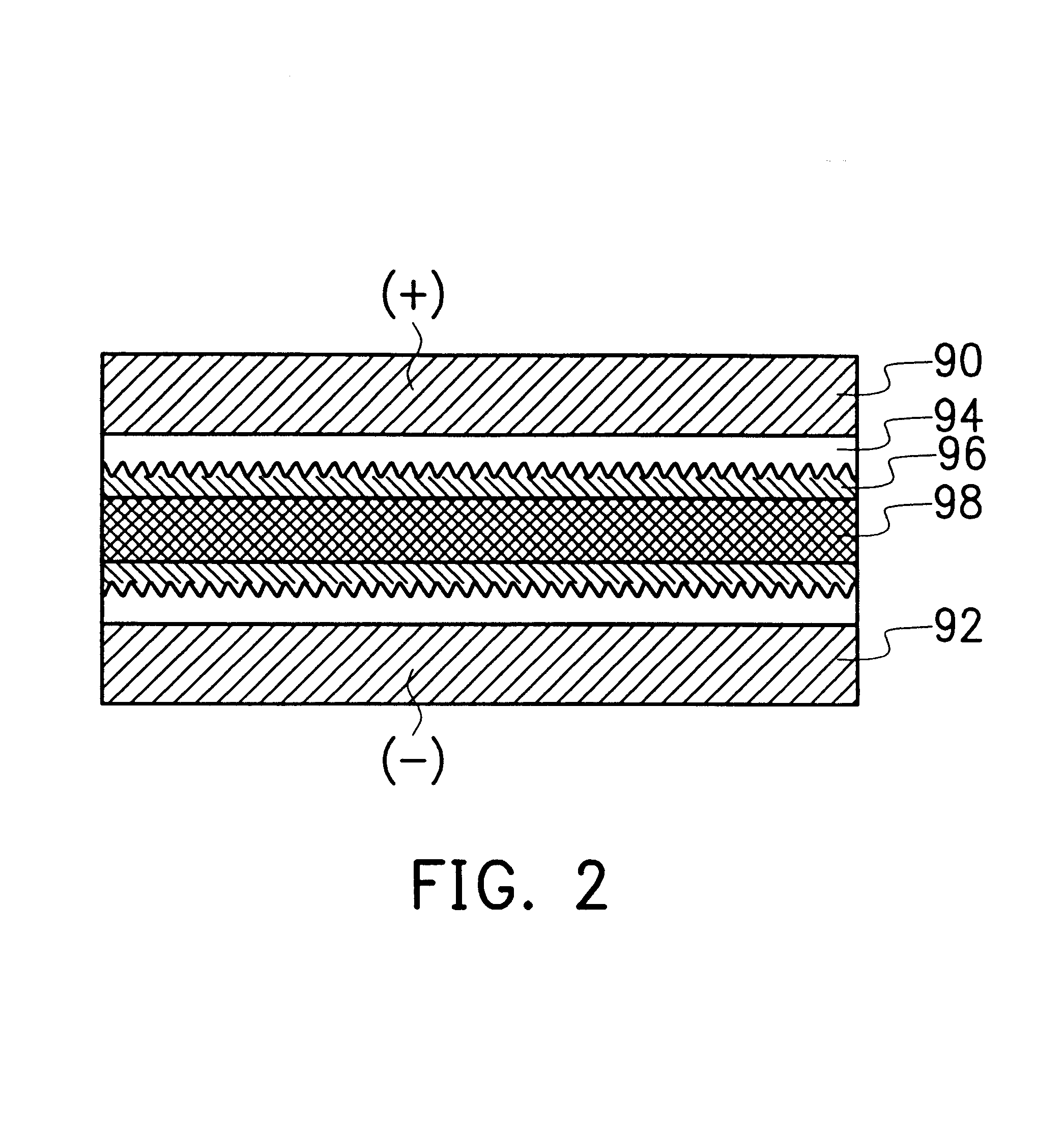
FIG. 2 is a cross-sectional view, schematically illustrating a basic structure of the supercapacitor, according to the invention. In FIG. 2, the supercapacitor basically includes an upper electrode plate 90, a lower electrode plate 92, and a dielectric layer between the two electrode plates 90, 92. According to the invention, the dielectric layer is formed including, for example, an active material layer 94, an electrolyte layer 96, and an isolation layer 98. Since the dielectric layer of the invention is suitable for use with respect to any geometric form of the electrode plate. The electrode plate 90, 92 can be a house of an appliance. The electrode plate 90 can be formed into a desired shape. An example is provided with a geometric form.
1 mm-thick carbon steel plates were cut and folded into 1.8 cm.times.3.8 cm.times.9.9 cm and 1.6 cm.times.3.6 cm.times.9.9 cm. As shown in FIG. 3, the smaller U-shaped plate 102 can fit snugly into the bigger U-shaped plate 100 with 1 mm space bet...
example 2
FIG. 4 shows another shape of substrates consisting of two concentric tubes of 1 mm-thick galvanized cast iron. When the tubes constitute a capacitor, only the surfaces opposing to each other are effective in providing capacitance. It is measured that the inside diameter of the larger tube 106 is 2.8 cm, while the outside diameter of the smaller tube 108 is 2.6 cm. Thus, there is a gap 110 of 2 mm between the iron tubes, and the gap is to be filled with a separator and an electrolyte. Three different lengths, 2 cm, 5 cm and 10 cm, of the iron tubes were used for testing. Thin-film of iron oxide were deposited on the inside surface of the larger tubes, as well as on the outside surface of the smaller tubes following the same procedures as Example 1. Following the CV measurement as Example 1, three concentric-tube-electrodes, at different length, were analyzed. The results are listed in Table 1:
TABLE 1 Supercapacitiors in Tube Configuration Length (cm) 2 5 10 Effective Area (cm.sup.2)...
example 3
This example illustrates how the present invention converts a non-iron substrate into monolithic electrodes for supercapacitors. FIG. 5 is a flow chart of converting aluminum to the iron-oxide electrode. Firstly, a 40 mil-thick plain aluminum foil was cut to 8 cm.times.8 cm at step 500. In step 502, the substrates were cleaned in an aqueous solution containing 30 g of S-438PC cleaner (Schlotter GmbH, Germany) in 1 liter de-ionized water at 50.degree. C. for 1 minute. Then, the substrates were removed, rinsed with DI water, and the substrates were subjected to activation of step 504. In which 25% HNO.sub.3 solution was applied to the substrates for 20 sec at the ambient. Following DI water rinsing, a chemical conversion known as zincating denoted by Zincate 1 of step 506 was conducted on the substrates using a commercial conditioner (SBZ from Schlotter) at 25% concentration in DI water under room temperature for 30 sec. In the conversion, a thin layer of zinc was deposited on the alu...
PUM
| Property | Measurement | Unit |
|---|---|---|
| Capacitance | aaaaa | aaaaa |
| Dielectric constant | aaaaa | aaaaa |
| Thickness | aaaaa | aaaaa |
Abstract
Description
Claims
Application Information
 - R&D
- Intellectual Property
- Life Sciences
- Materials
- Tech Scout
- Unparalleled Data Quality
- Higher Quality Content
- 60% Fewer Hallucinations
Browse by: Latest US Patents, China's latest patents, Technical Efficacy Thesaurus, Application Domain, Technology Topic, Popular Technical Reports.
© 2025 PatSnap. All rights reserved.Legal|Privacy policy|Modern Slavery Act Transparency Statement|Sitemap|About US| Contact US: help@patsnap.com


