Circumferential flow pump

a flow pump and circumferential flow technology, applied in the direction of machines/engines, mechanical equipment, liquid fuel engines, etc., can solve the problems of impeller lock, large volume of alcohol and toluene swelling, and clogging of injection molding resin

Inactive Publication Date: 2007-08-09
MITSUBISHI ELECTRIC CORP
View PDF1 Cites 8 Cited by
  • Summary
  • Abstract
  • Description
  • Claims
  • Application Information

AI Technical Summary

Benefits of technology

[0013]According to the present invention, because a circumferential flow pump having an impeller made of fiber-reinforced PPS is provided, the quantity of swel...

Problems solved by technology

In conventional circumferential flow pumps, resin's flow during injection molding tends to be blocked due to bends on the vane portion.
Consequently, due to the low randomness of fiber-orientation in the vane portion and the ring ...

Method used


Image

  • Circumferential flow pump
  • Circumferential flow pump
  • Circumferential flow pump

Examples


embodiment 1

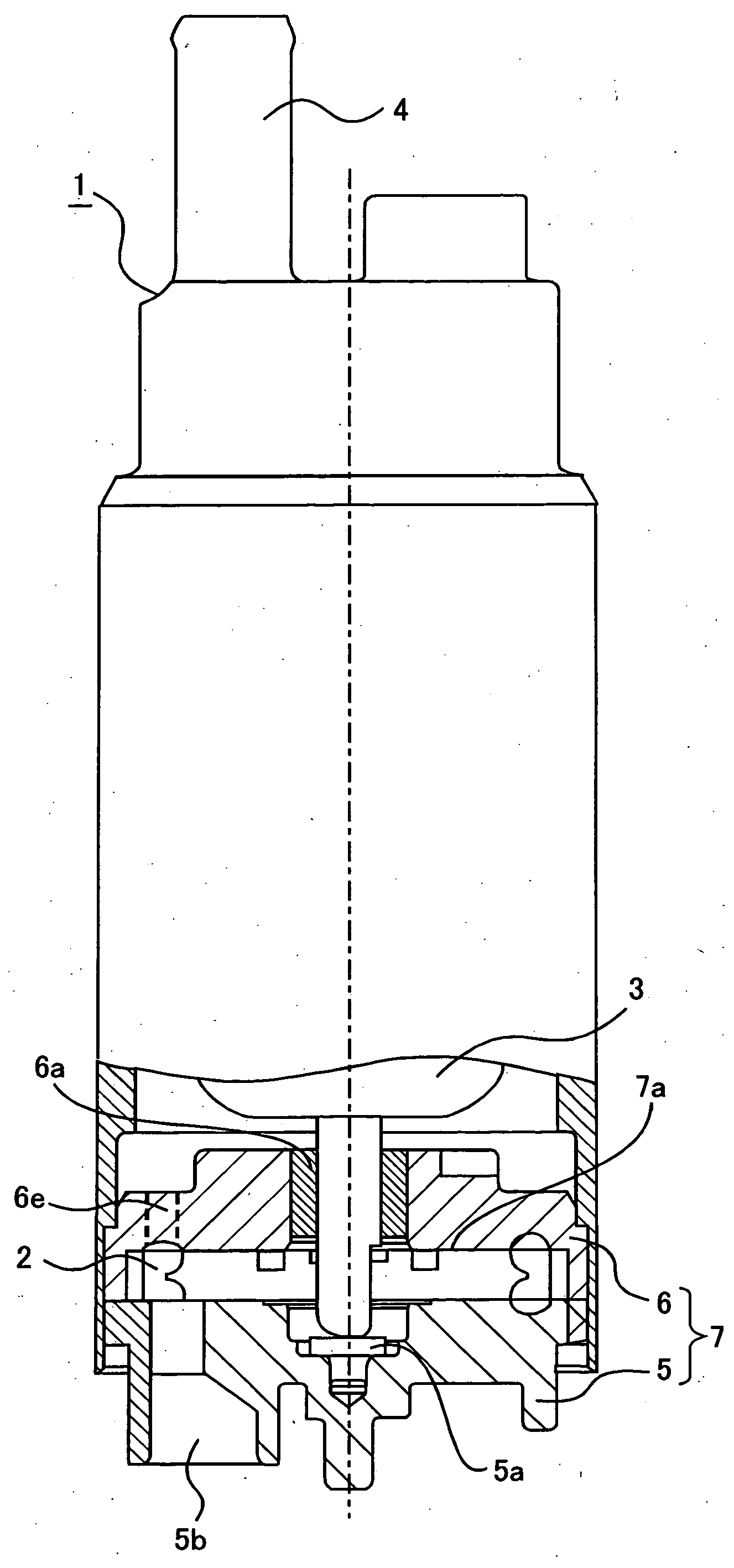
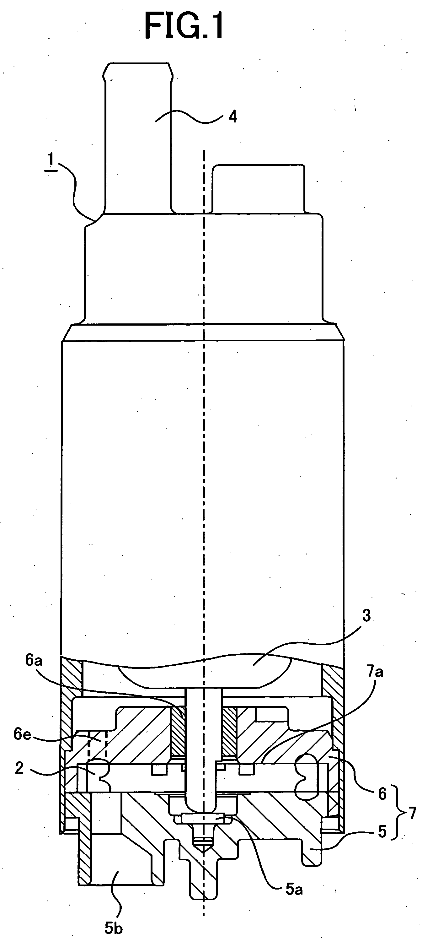
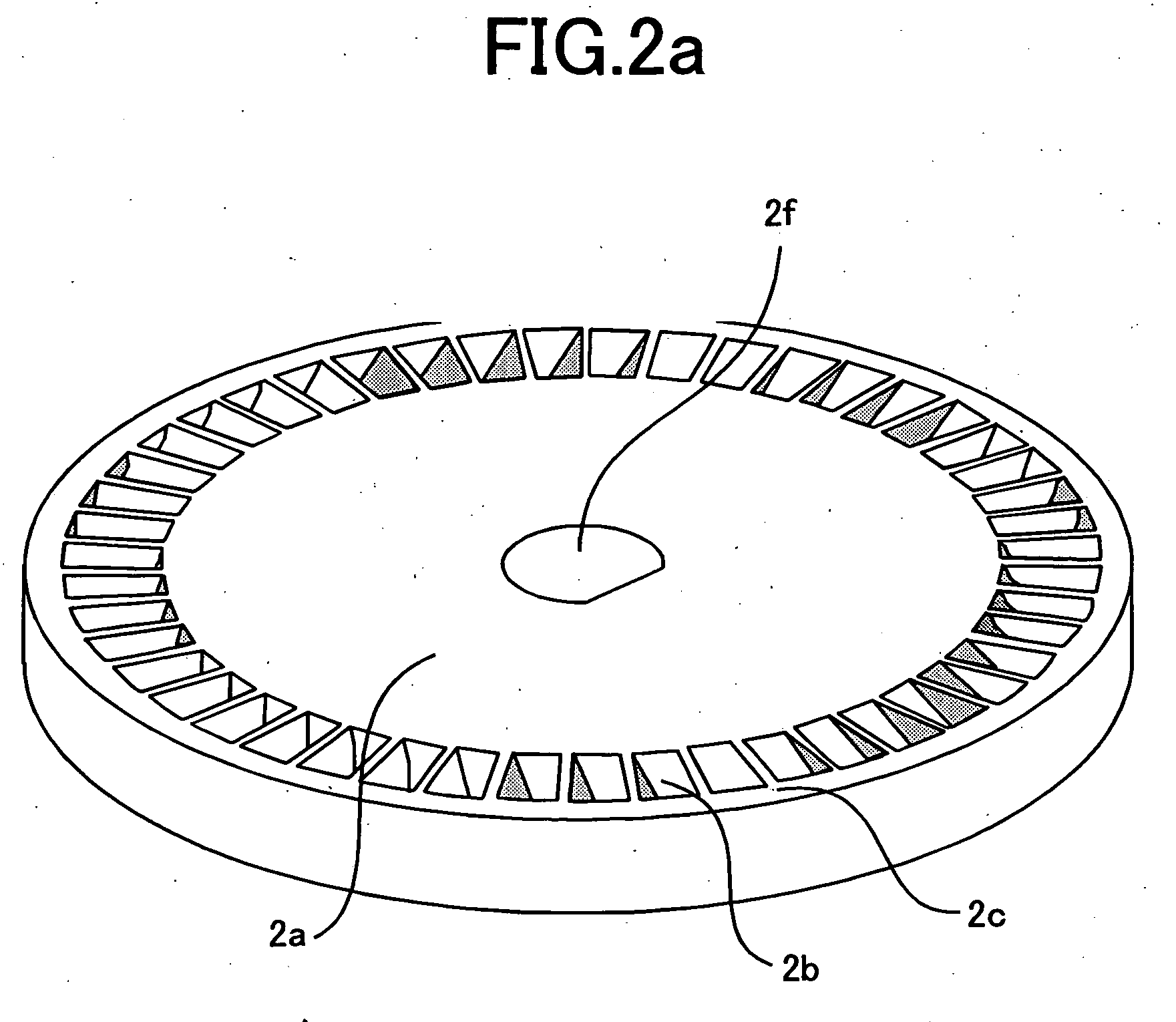
[0017]FIG. 1 is a partially sectional elevation view illustrating a circumferential flow pump in Embodiment 1. The circumferential flow pump 1 includes: a disc-shaped impeller 2 fitted to the motor rotor 3; and a pump-housing 7, composed of a pump cover 5 and a pump base 6 for housing the impeller 2. In the pump cover 5, a thrust bearing 5a is placed at the center thereof for bearing in the thrust direction the shaft of the motor rotor 3, and an inlet 5b is provided at the bottom of the cover for leading from a fuel tank, fuel into the impeller 2. At the center of the pump base 6, a metal member 6a is placed for bearing the rotating shaft of the rotor 3.

[0018]When the motor rotor 3 is driven with the pump 1 being immersed in the fuel tank, the fuel is led from the inlet 5b into the pump room by the rotation of the impeller 2. Through an outlet 6e of a pump room and the motor room, the fuel is sent from a spout 4 to the internal combustion engine. In addition, in order to prevent the...


PUM


Abstract

A circumferential flow pump in which the quantity of swelling by alcohol or toluene contained in fuel, is curbed and an impeller thereof is prevented from locking is provided.
A circumferential flow pump for feeding into an internal combustion engine, fuel from the fuel tank thereof includes an impeller, made of fiber-reinforced PPS, having a base portion fitted to a motor rotor, a vane portion provided outer-circumferentially on the base portion, and an outer ring portion provided outer-circumferentially on the vane portion; the vane portion is composed of a plurality of vanes arranged radially protruding straightly from the base portion and each vane includes a bend thereon; and furthermore, given that a projected area of the entire vane portion is S1, that of the ring portion, S2, that of the base portion, S3, when the impeller, is projected from a direction along a motor shaft of the motor rotor, the ratio of S3 to S1 is made to fall between 9:1 to 15:1, and the ratio of S2 to S1 is made to fall between 0.10:1 to 0.13:1.

Description

BACKGROUND OF THE INVENTION[0001]1. Field of the Invention[0002]The present invention relates to circumferential flow pumps that are housed in the fuel tank of, for example, an automobile, and supply fuel to the internal combustion engine thereof at a predetermined pressure.[0003]2. Description of the Related Art[0004]An impeller mounted on a circumferential flow pump is provided with a base portion that is fitted to a motor rotor, a vane portion that is formed outer-circumferentially on the base portion, and an outer ring portion that is formed outer-circumferentially on the vane portion. In conventional circumferential flow pumps, impellers have being developed for the purpose of raising efficiency or lowering noise. As an impeller of this king, it is known that the vane portion is made thinner, and that fiber-reinforced polyphenylene sulfide(PPS), being excellent in moldability and dimensional stability, is used. It is also known that a bend is formed on each vane (e.g., Japanese...

Claims


Application Information

Patent Timeline
IPC IPC(8): F04D5/00
CPCF04D5/002F04D29/188F04D29/026F05D2300/43F05D2300/603
Inventor KOYAMA, MASAHIROINOUE, SEIZOU
Owner MITSUBISHI ELECTRIC CORP
Why Eureka
Try Eureka