Boundary wall with reinforcement device

a technology of reinforcement device and boundary wall, which is applied in the direction of edging using tiles, structural elements, building components, etc., can solve the problems of side walls prone to shift and/or distort, coupling elements that cannot completely prevent any axial distortion of construction elements mounted to each other, and excessive material stress, so as to prevent their distortion and prevent any excessive additional costs

a technology of reinforcement device and boundary wall, which is applied in the direction of edging using tiles, structural elements, building components, etc., can solve the problems of side walls prone to shift and/or distort, coupling elements that cannot completely prevent any axial distortion of construction elements mounted to each other, and excessive material stress, so as to prevent their distortion and prevent any excessive additional costs

US20130025195A1Active Publication Date: 2013-01-31WUSTER HEINRICH

Image

  • Boundary wall with reinforcement device
  • Boundary wall with reinforcement device
  • Boundary wall with reinforcement device

Examples


Embodiment Construction

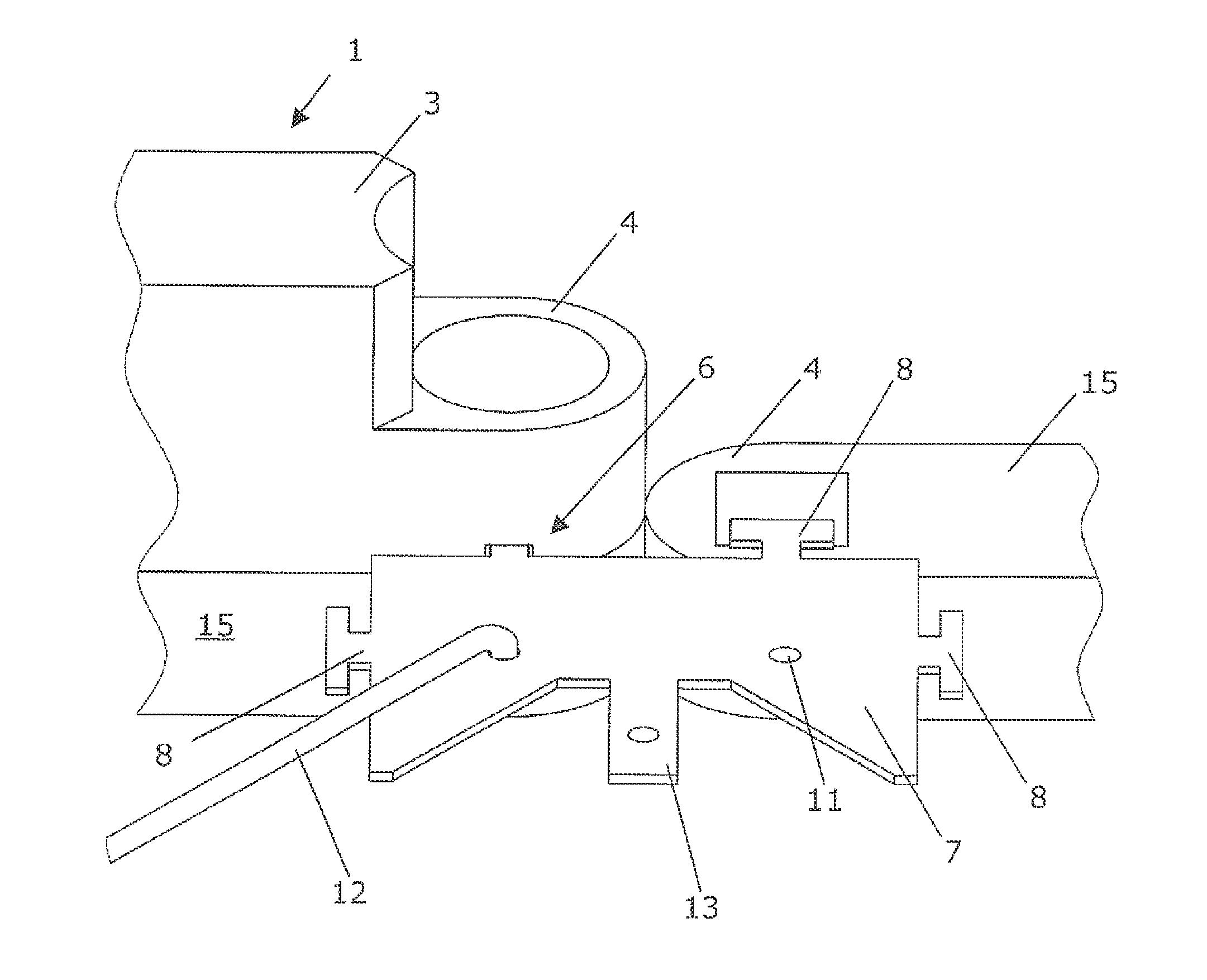
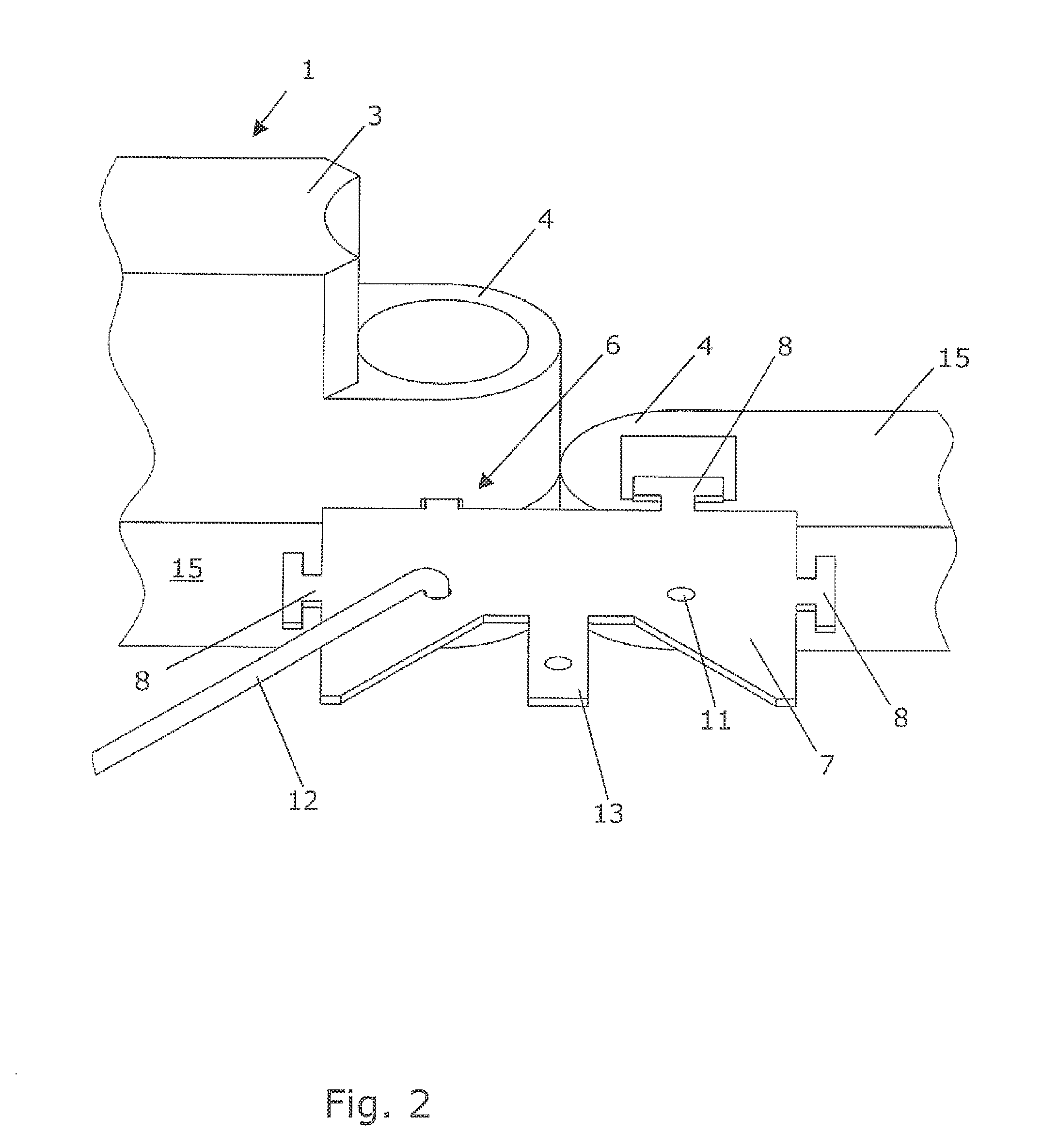
[0035]FIG. 2 illustrates a schematic illustration of a boundary wall in accordance with embodiments of the invention with a first construction element 1 and a pair of base elements 15. The first construction element 1 includes a base body 3, having at projecting end section thereof a connection element 4. A slot 6 being provided in the connection elements 4 and configured to receive a corresponding coupling bar 8 of a first coupling element 7. The second construction element 2, which is also placed upon a corresponding base body 15, is not illustrated in this exemplary embodiment. The coupling element 7 has a projection 13 extending therefrom and a plurality of openings 11 sized to receive by insertion a bar 12. Each base element 15 is configured to receive a corresponding one of the construction elements 1, 2.

[0036]FIG. 3 illustrates the first coupling element 7 in accordance with embodiments of the invention, which includes a plurality of coupling bars 8 at its circumference. Each...


PUM


Abstract

A boundary wall for framing beds, hotbeds, boundaries in gardens and green areas that includes construction elements configured for connection to each other. Each construction element includes a base body with projecting end sections having connection elements configured to support coupling elements. The connection elements also receive by form-fit at least one reinforcing coupling element which thereby connect the construction elements to each other and / or with other construction elements.

Description

CROSS-REFERENCE TO RELATED APPLICATIONS[0001]The present application claims priority under 35 U.S.C. §119 to Austrian Patent Application No. A1112 / 2011 (filed on Jul. 29, 2011), which is hereby incorporated by reference in its entirety.FIELD OF THE INVENTION[0002]The invention relates to a boundary wall for framing beds, hotbeds, boundaries in garden or green areas or the like, and includes elongated construction elements that can be interconnected, each including a base body having projecting end sections at its faces with connection elements formed thereat to accept coupling elements.BACKGROUND OF THE INVENTION[0003]Several devices are known from the prior art for the creation of boundary wails for framing beds, hotbeds, boundaries in gardens or green areas or the like.[0004]FIG. 1 illustrates a prior art boundary wall that includes a pair of oblong construction elements 1, 2. The construction elements 1, 2 each include a base body 3, showing at its face projecting end sections wi...

Claims


Application Information

Patent Timeline
31 Jan 2013
Publication
US20130025195A1
IPC
A01G1/08; E04B1/38; E04B2/00; A01G9/28
CPC
A01G1/08; A01G9/28
Inventors
WUSTER, HEINRICH