Process for Removing Carbon Dioxide From a Gas Stream using Desublimation

a technology of carbon dioxide and gas stream, which is applied in the direction of separation processes, liquefaction, lighting and heating apparatus, etc., can solve the problems of significant additional investment and operating costs of industrial plants, increase of electricity costs in the range of 4 to 5 u.s. cents/kwh, and equipment addition, etc., to achieve high efficiency

Inactive Publication Date: 2013-01-31
LAIR LIQUIDE SA POUR LETUDE & LEXPLOITATION DES PROCEDES GEORGES CLAUDE
View PDF10 Cites 18 Cited by
  • Summary
  • Abstract
  • Description
  • Claims
  • Application Information

AI Technical Summary

Benefits of technology

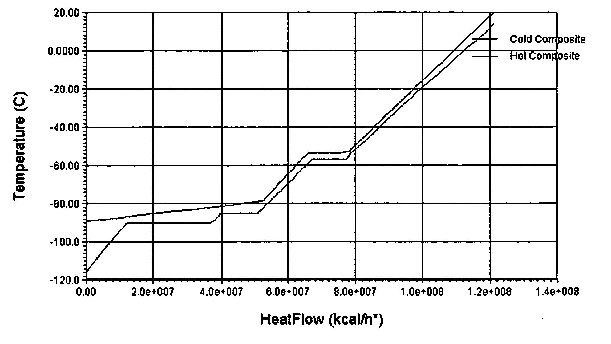
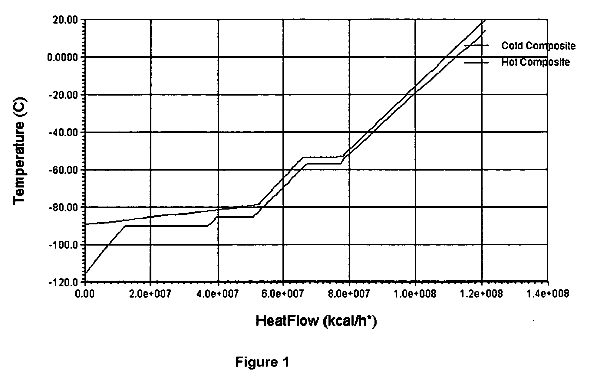
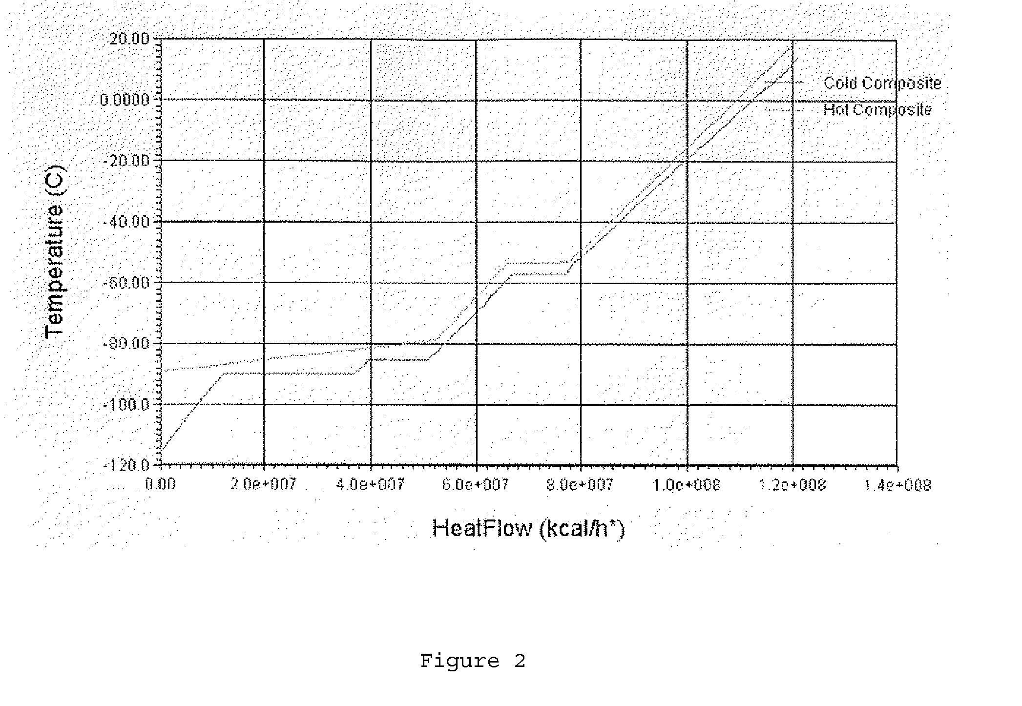
[0008]The present invention relates to a highly efficient auto-refrigerated process for de-sublimation of a flue gas. In this process, the flue gas is first compressed to a medium range. This compressed flue gas is then cooled before being subjected to a partial desublimation to produce solid carbon dioxide and cold medium pressure flue gas. The solid carbon dioxide is then separated from the cold medium pressure flue gas. The cold medium pressure flue gas is then introduced into an expansion turbine where additional solid carbon dioxide is formed and the pressure of the flue gas is dropped to a low range. This additional solid carbon dioxide is then separated from the low pressure flue gas to produce a carbon dioxide depleted flue gas. The low pressure carbon dioxide depleted flue is gas heated to recover sensible heat. The solid carbon dioxide is split into at least two streams with part of the solid carbon dioxide being brought to or above triple point pressure and liquefied. Sensible heat of the solid and the liquid is recovered as well as fusion heat of the solid when liquefied. The remaining part of the solid is brought to lower pressure (sub-atmospheric pressure) and vaporized at low pressure. Sublimation heat of the low pressure carbon dioxide is recovered to heat exchange with de-sublimating flue gas. Gaseous sub-atmospheric pressure carbon dioxide is then compressed by sub-atmospheric compression means. A portion of this can be compressed to a pressure high enough to be condensed at ambient temperature and then pumped to final pressure. The remaining part can be compressed to an intermediate pressure and condensed at a lower pressure by heat exchange with the rest of the process.

Problems solved by technology

However, these technologies involve significant additional investment and operating costs for industrial plants.
For example, in the case of coal power plants a resulting increase of the cost of electricity in the range of 4 to 5 U.S. cents / kWh is expected.
However, there is no mention in the literature of a process that would simultaneously work at a relatively low pressure and require no external refrigeration.
This external loop adds equipment and decreases the overall efficiency of the process.

Method used


Image

  • Process for Removing Carbon Dioxide From a Gas Stream using Desublimation
  • Process for Removing Carbon Dioxide From a Gas Stream using Desublimation
  • Process for Removing Carbon Dioxide From a Gas Stream using Desublimation

Examples


Embodiment Construction

[0033]The present process relates to a more efficient process for the removal of carbon dioxide from a carbon dioxide containing stream. By capturing the energy associated with the transition of solid carbon dioxide to either a liquid or vapor, it is possible to eliminate or at least significantly minimize the use of the external cooling systems such as additional refrigerant loops including compressors as well as the cooling means for compressed refrigerant that have previously been used in the prior art systems of carbon dioxide removal. The process may be carried out in a direct manner in which the use of the prior art external cooling systems are eliminated or in an indirect manner in which the prior art external cooling systems are minimized (used only to bolster the process).

[0034]With regard to the carbon dioxide containing gas streams that may be treated utilizing either embodiment of the present invention, such streams may be provided from a variety of sources, including bu...


PUM


Abstract

A process for removing carbon dioxide from a carbon dioxide containing gas stream is obtained through de-sublimation, vaporization, and liquefaction of various carbon dioxide-containing streams with little or no external refrigeration.

Description

CROSS-REFERENCE TO RELATED APPLICATIONS[0001]This application claims the benefit of U.S. Provisional Application No. 61 / 497,148, filed Jun. 15, 2011.FIELD OF THE INVENTION[0002]The present invention relates to a cost effective, efficient process for capturing carbon dioxide from a gas stream using desublimation.BACKGROUND[0003]The emission of carbon dioxide from fossil fuel combustion is a growing source of concern around the world. Numerous technologies have been developed to address this problem. Research and development continue in this area. One avenue of research has concentrated on the capture of carbon dioxide from flue gas and other gas streams. Some of the major technologies utilized have included amine washes, physical adsorption technologies, cryogenic technologies (carbon dioxide liquefaction) and such. However, these technologies involve significant additional investment and operating costs for industrial plants. For example, in the case of coal power plants a resulting...

Claims


Application Information

Patent Timeline
Patent Type & Authority Applications(United States)
IPC IPC(8): F25J1/00
CPCB01D53/002F25J2270/80B01D2257/10B01D2258/0283B01D2259/65F25J3/067F25J2205/20F25J2210/70F25J2220/82F25J2230/80F25J2235/80F25J2270/04Y02C10/12F25J2230/30B01D2256/22Y02C20/40
Inventor TERRIEN, PAULTESSIER, PASCAL
Owner LAIR LIQUIDE SA POUR LETUDE & LEXPLOITATION DES PROCEDES GEORGES CLAUDE
Why Eureka
Try Eureka