Waterjet cutting system with standoff distance control

a cutting system and waterjet technology, applied in the field of waterjet cutting systems, can solve problems such as system shutdown, possible damage to workpieces, taper and trailback, etc., and achieve the effect of high efficiency and accurate manner

Active Publication Date: 2013-01-31
FLOW INT
View PDF51 Cites 67 Cited by
  • Summary
  • Abstract
  • Description
  • Claims
  • Application Information

AI Technical Summary

Benefits of technology

[0008]Embodiments described herein provide waterjet cutting systems and methods particularly well adapted for processing workpieces in a highly efficient and accurate manner by providing momentary, intermittent or continuous feedback of a waterjet nozzle standoff distance. Embodiments include a cutting head having an environment control device and a measurement device integrated therewith in a particularly compact form factor or package.

Problems solved by technology

These cut characteristics, namely taper and trailback, may or may not be acceptable, given the desired end product.
If the standoff distance is too small, the nozzle can plug during piercing, causing system shutdown and possibly damage to the workpiece.
If the distance is too great, the quality and accuracy of the cut suffers.
These types of systems therefore often include features which may limit, for example, the mobility and / or flexibility of the waterjet cutting system to traverse a workpiece in a particularly advantageous cutting path.
In addition, components of these systems may be unavoidably exposed to spray-back which occurs when the waterjet first impinges on a surface of a workpiece or as the waterjet interacts with a structure beneath the workpiece during operation, thereby leading to potential wear and damage of the components.

Method used


Image

  • Waterjet cutting system with standoff distance control
  • Waterjet cutting system with standoff distance control
  • Waterjet cutting system with standoff distance control

Examples


Embodiment Construction

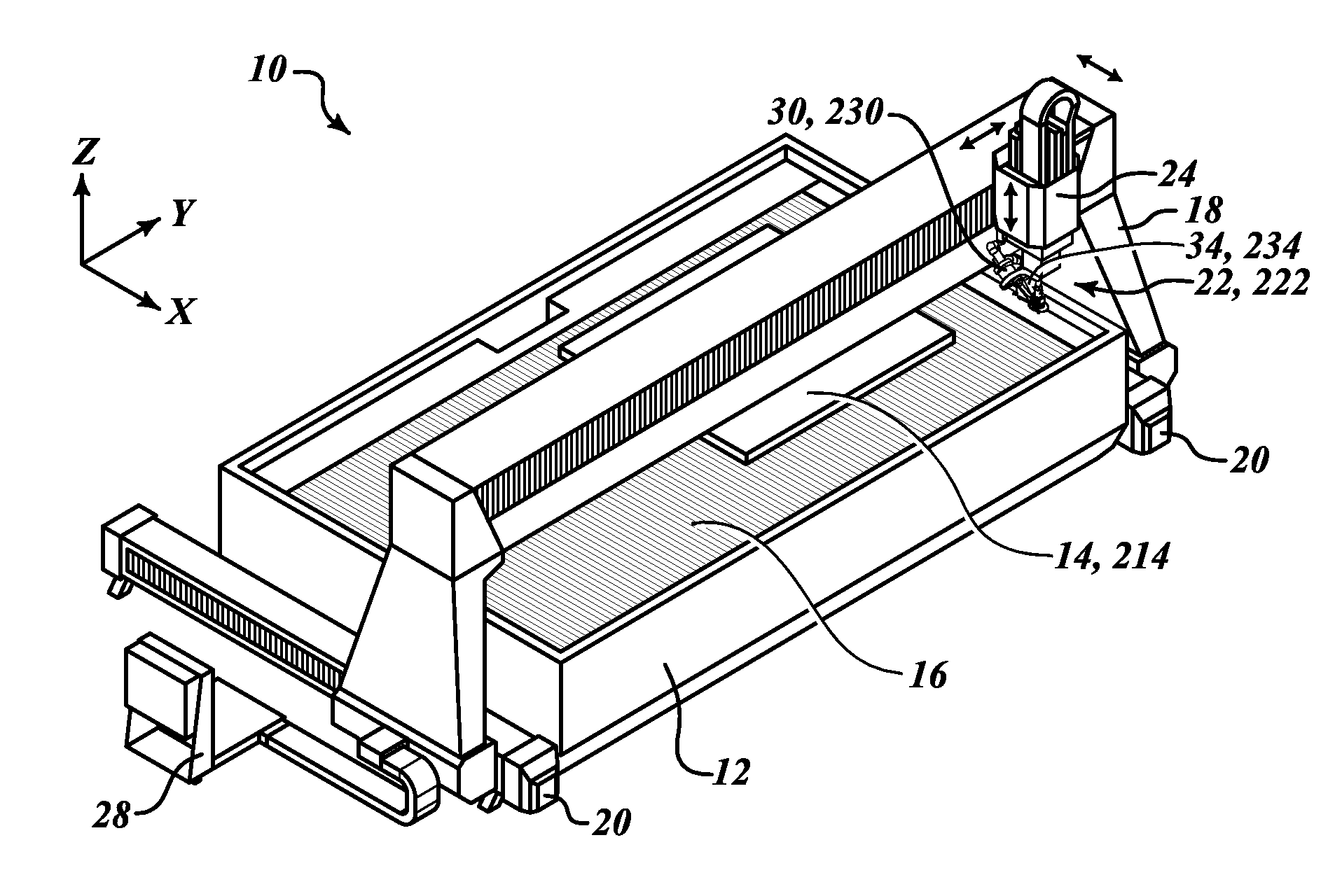
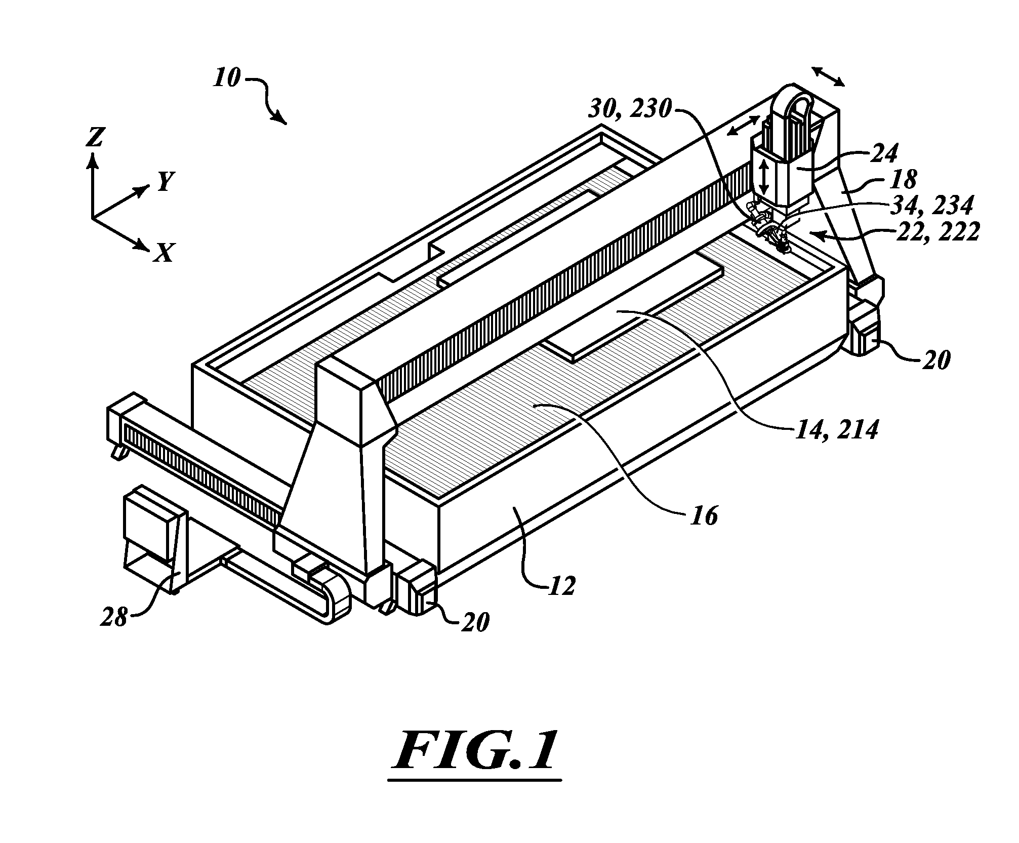
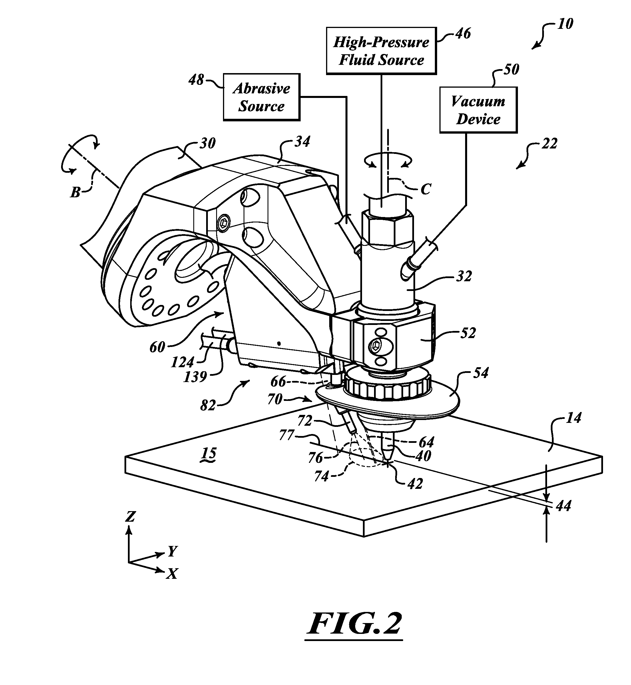
[0055]In the following description, certain specific details are set forth in order to provide a thorough understanding of various disclosed embodiments. However, one of ordinary skill in the relevant art will recognize that embodiments may be practiced without one or more of these specific details. In other instances, well-known structures associated with waterjet cutting systems and methods of operating the same may not be shown or described in detail to avoid unnecessarily obscuring descriptions of the embodiments. For instance, it will be appreciated by those of ordinary skill in the relevant art that a high-pressure fluid source and an abrasive source may be provided to feed high-pressure fluid and abrasives, respectively, to a cutting head of the waterjet systems described herein to facilitate, for example, high-pressure or ultrahigh-pressure abrasive waterjet cutting of workpieces. As another example, well know control systems and drive components may be integrated into the w...


PUM

PropertyMeasurementUnit
standoff distanceaaaaaaaaaa
pressureaaaaaaaaaa

Abstract

A cutting head of a waterjet cutting system is provided having an environment control device and a measurement device. The environment control device is positioned to act on a surface of a workpiece at least during a measurement operation to establish a measurement area on the surface of the workpiece substantially unobstructed by fluid. The measurement device is positioned to selectively obtain information from within the measurement area indicative of a position of the cutting head relative to the workpiece. A control system is further provided and operable to position the cutting head relative to the workpiece at a standoff distance based at least in part on the information indicative of the position of the cutting head relative to the workpiece obtained by the measurement device. A method of operating a waterjet cutting system is also provided.

Description

BACKGROUND[0001]1. Technical Field[0002]This disclosure is related, generally, to waterjet cutting systems, and, in particular, to a method and apparatus for controlling a standoff distance between a waterjet cutting head and a surface of a workpiece to be processed.[0003]2. Description of the Related Art[0004]Fluid jet or abrasive-fluid jet cutting systems are used for cutting a wide variety of materials, including stone, glass, ceramics and metals. In a typical fluid jet cutting system, a high-pressure fluid (e.g., water) flows through a cutting head having a cutting nozzle that directs a cutting jet onto a workpiece. The system may draw an abrasive into the high-pressure fluid jet to form an abrasive-fluid jet. The cutting nozzle may then be controllably moved across the workpiece to cut the workpiece as desired. After the fluid jet, or abrasive-fluid jet, generically referred to throughout as a “waterjet,” passes through the workpiece, the energy of the cutting jet is dissipated...

Claims


Application Information

Patent Timeline
Patent Type & Authority Applications(United States)
IPC IPC(8): B26F1/26
CPCB24C1/045B24C5/02B26F3/004B26D5/00B24C9/00B24C5/00Y10T83/0443Y10T83/0591Y10T83/242Y10T83/364Y10T83/527
Inventor CHILLMAN, ALEX M.EIDE, KIRBY J.SCHUMAN, BRUCE M.TANUMA, AKIVAUGHAN, SEAN A.CHENOWETH, II, RAYMOND L.HAGEMAN, III, RICHARD B.CRAIGEN, STEVEN J.HASHISH, MOHAMED A.BURNHAM, CHARLES D.
Owner FLOW INT
Why Eureka
Try Eureka