Display device
a display device and display technology, applied in the field of display devices, can solve the problems of low backlight unit efficiency, high energy consumption, and not so fast response tim
- Summary
- Abstract
- Description
- Claims
- Application Information
AI Technical Summary
Benefits of technology
Problems solved by technology
Method used
Image
Examples
first embodiment
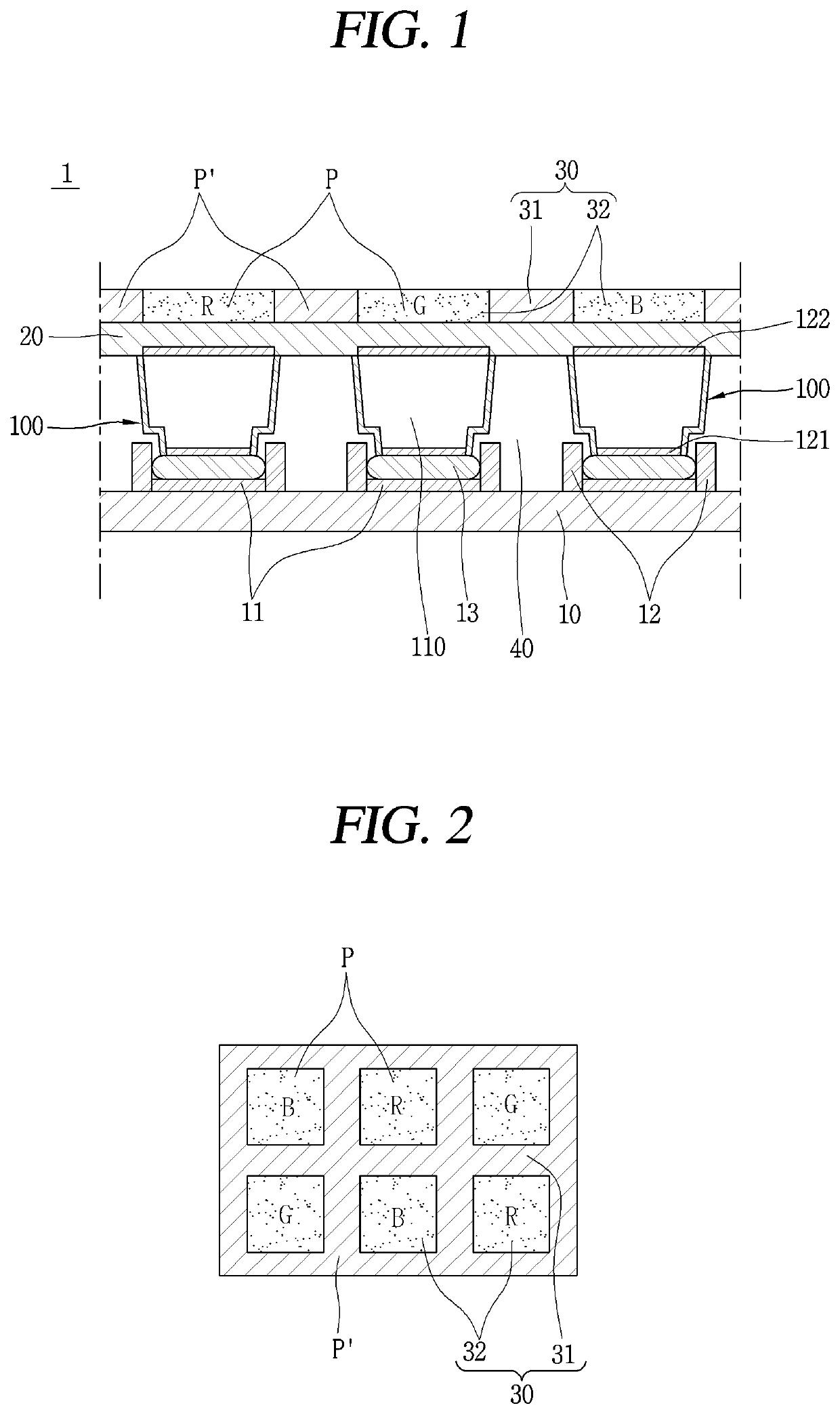
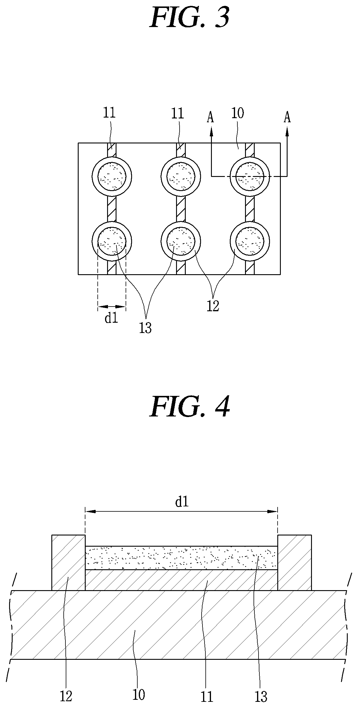
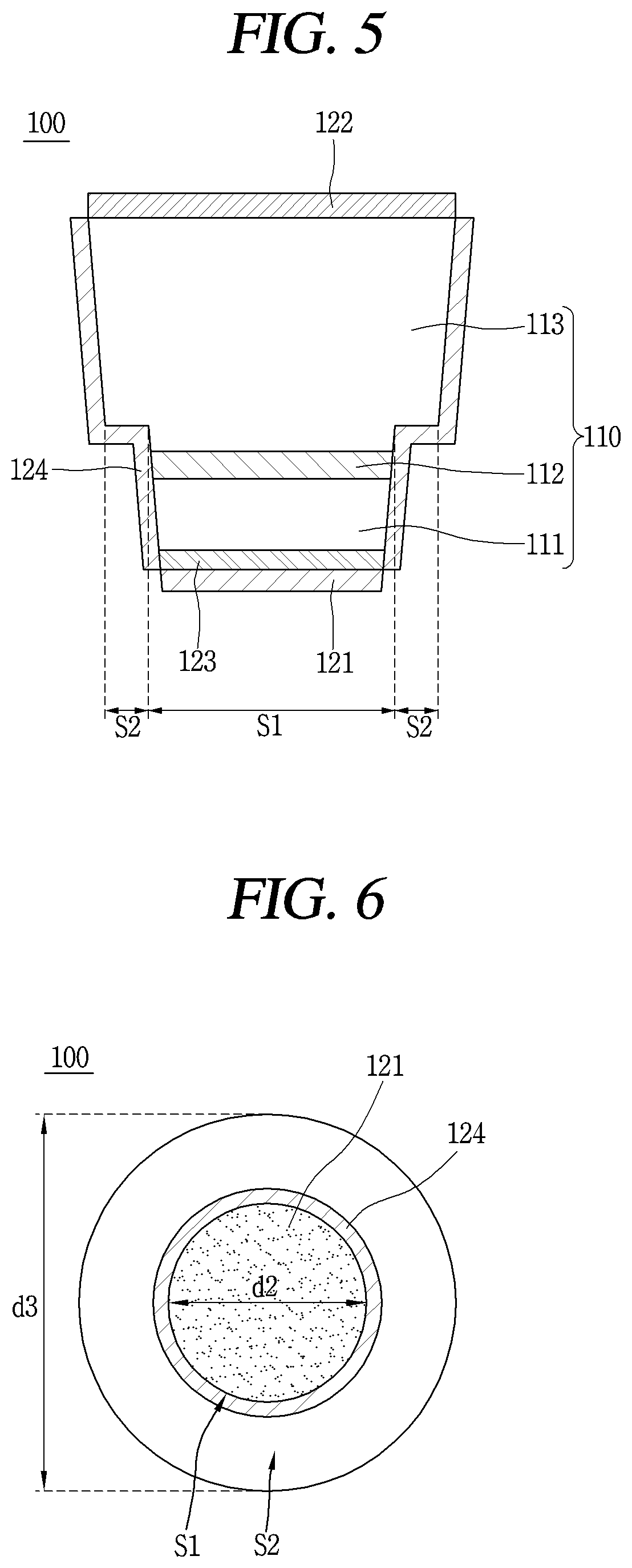
[0058]Referring to FIGS. 1 to 4, a display device 1 includes a lower substrate 10 on which lower wiring 11 is disposed, and at least two light-emitting devices (or elements) 100 each having a first electrode 121 electrically connected to the lower wiring 11 and a light-emitting structure 110 configured to generate light.
[0059]In addition, the display device 1 according to the first embodiment further includes a second electrode 122 located on a second conductive semiconductor layer 113, an upper wiring 20 electrically connected to the second electrode 122, and a color substrate 30 disposed on the light-emitting device 100 to convert a wavelength of light generated from the light-emitting device 100.
[0060]The lower substrate 10 may be implemented as a film made of an insulating material. For example, the lower substrate 10 may be made of a transparent glass material, or may be made of a transparent plastic or a polymer film having high flexibility.
[0061]The lower wiring 11 is dispos...
second embodiment
[0150]The display device 1A includes the lower substrate 10 on which at least two lower wirings 11 are disposed, at least two light-emitting devices 100A each having the first electrode 121 electrically connected to the lower wiring 11 and the light-emitting structure 110 that generates light, and the magnetic portion located on any one of the light-emitting device 100A and the lower substrate 10, and the reaction portion located on the remaining one, so as to be attracted by the magnetic portion.
[0151]In the second embodiment, the positioning partition wall 12 of the first embodiment is not provided. In the second embodiment, one light-emitting device 100A is self-aligned in one pixel region P by a magnetic force acting between the magnetic portion and the reaction portion.
[0152]The metal bonding layer 13 is disposed on the lower wiring 11 in an area where the light-emitting device 100A is to be located, as in the first embodiment.
[0153]The light-emitting device 100A of the second...
third embodiment
[0172]FIG. 13 is a cross-sectional view of a display device according to the present disclosure.
[0173]Referring to FIG. 13, a display device 1B according to the third embodiment further includes a second magnetic portion 15 and a second magnetic electrode 132, as compared to the second embodiment.
[0174]The magnetic portion may include the first magnetic portion 14 and the second magnetic portion 15, or include only the second magnetic portion 15 or only the first magnetic portion 14. In FIG. 13, the magnetic portion includes the first magnetic portion 14 and the second magnetic portion 15.
[0175]When a magnetic force of the magnetic portion is weak, a possibility of proper alignment of the light-emitting device 100A decreases, and thus a plurality of magnetic portions may be provided. That is, a plurality of magnetic portions is provided in one pixel region P.
[0176]The second magnetic portion 15 is located at the lower surface of the lower substrate 10. In detail, the second magnetic...
PUM
| Property | Measurement | Unit |
|---|---|---|
| voltage | aaaaa | aaaaa |
| melting point temperature | aaaaa | aaaaa |
| melting point temperature | aaaaa | aaaaa |
Abstract
Description
Claims
Application Information
 - R&D
- Intellectual Property
- Life Sciences
- Materials
- Tech Scout
- Unparalleled Data Quality
- Higher Quality Content
- 60% Fewer Hallucinations
Browse by: Latest US Patents, China's latest patents, Technical Efficacy Thesaurus, Application Domain, Technology Topic, Popular Technical Reports.
© 2025 PatSnap. All rights reserved.Legal|Privacy policy|Modern Slavery Act Transparency Statement|Sitemap|About US| Contact US: help@patsnap.com


