
Tuning an overhead valve internal combustion engine

a technology of overhead valve and internal combustion engine, which is applied in the direction of engine starters, mechanical measuring arrangements, instruments, etc., can solve the problems of difficult valve adjustment process, inaccessible, and inability to reach even a central location

Inactive Publication Date: 2013-01-31
CICCARONE THOMAS E
View PDF0 Cites 1 Cited by
  • Summary
  • Abstract
  • Description
  • Claims
  • Application Information

AI Technical Summary

Benefits of technology

The patent text describes a process for tuning a vehicle's engine that has overlapping valves. The process is suitable for vehicles that use a starter motor and have two cylinder heads with valves and springs. The valves have mechanisms that can open or close them by pressing on the valve stem. When the valves are closed, there is a small gap between the valve stem and the mechanism. The engine has two valve covers, one for each cylinder head. The valve mechanisms are activated by the engine starter motor. The technical effect of the process is to improve engine performance and efficiency by optimizing the timing of the valves' opening and closing.

Problems solved by technology

In some of these dragsters, the engine bumping push-button is mounted on one side of the vehicle, where it can be reached by an individual while making adjustments on the valves on that side, but is not readily accessible when the individual is working on the valves on the opposite side of the engine.
Thus, unless the individual making the adjustment has simian arms, he will not be able to reach even a centrally located engine bumping push-button while seated in a position for adjustment of the rearmost valves in a valve train.
The need to rise from the seated position repeatedly makes the process of valve adjustment difficult even in the case of a vehicle having a centrally located engine bumping push-button.
Reestablishing a proper two-handed grip on the feeler gauge following each engine bumping step increases the time required to carry out the gap-checking and valve adjusting operation.
Similar difficulties are encountered when checking valve springs using a force measuring gauge.
An individual carrying out valve adjustment encounters additional problems.

Method used


Image

  • Tuning an overhead valve internal combustion engine
  • Tuning an overhead valve internal combustion engine
  • Tuning an overhead valve internal combustion engine

Examples


Embodiment Construction

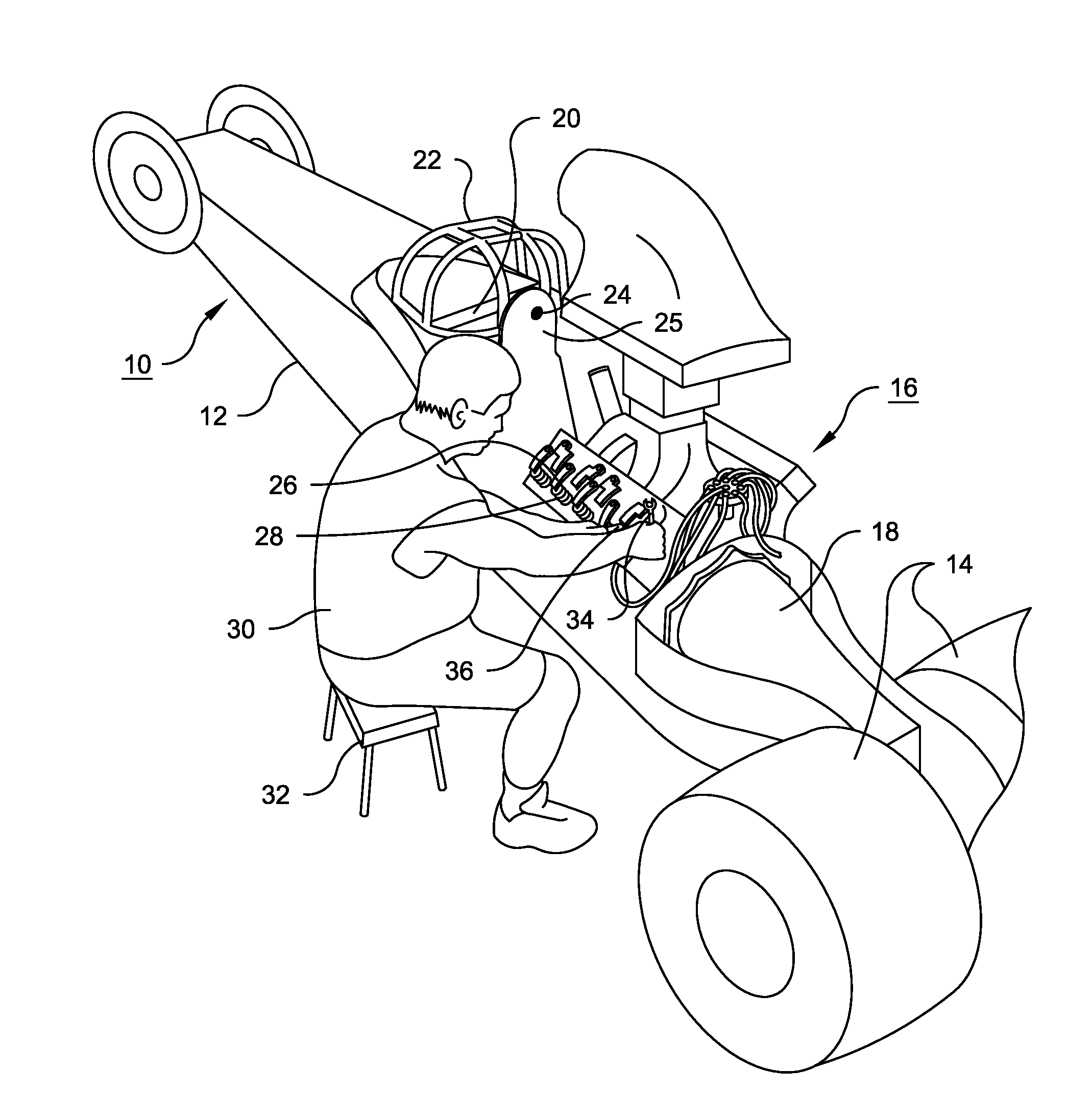
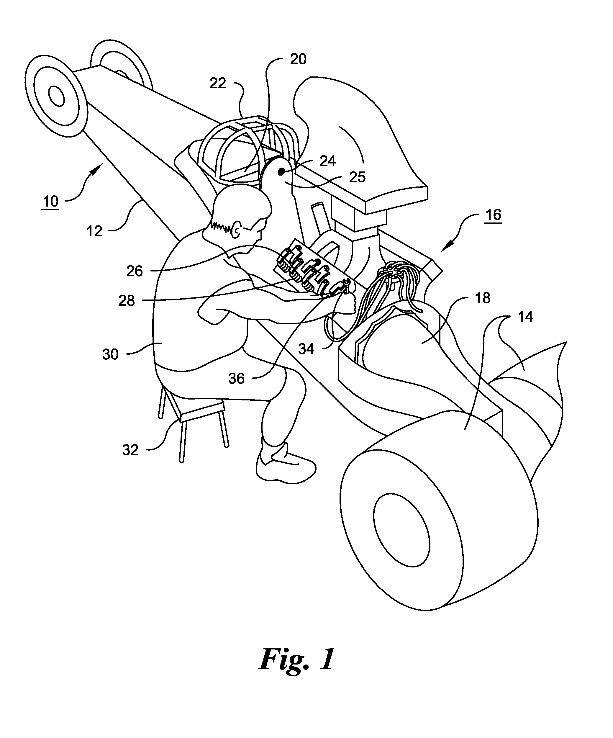
[0027]The dragster 10 shown in FIG. 1 comprises a rail frame 12 having a pair of large wheels 14 located at the rear of the vehicle, driven by an engine 16 through a transmission 18. The driver sits on a driver's seat 20, protected by a roll cage 22. An engine bumping push-button 24 is mounted on a panel 26 behind the driver's seat, at a location in front of the engine and at a central location between the sides of the vehicle. The left valve cover has been removed from the engine for access to the valve train, including valve-operating rocker arms, e.g., rocker arm 26, and valve springs, e.g., spring 28, both shown in FIG. 6

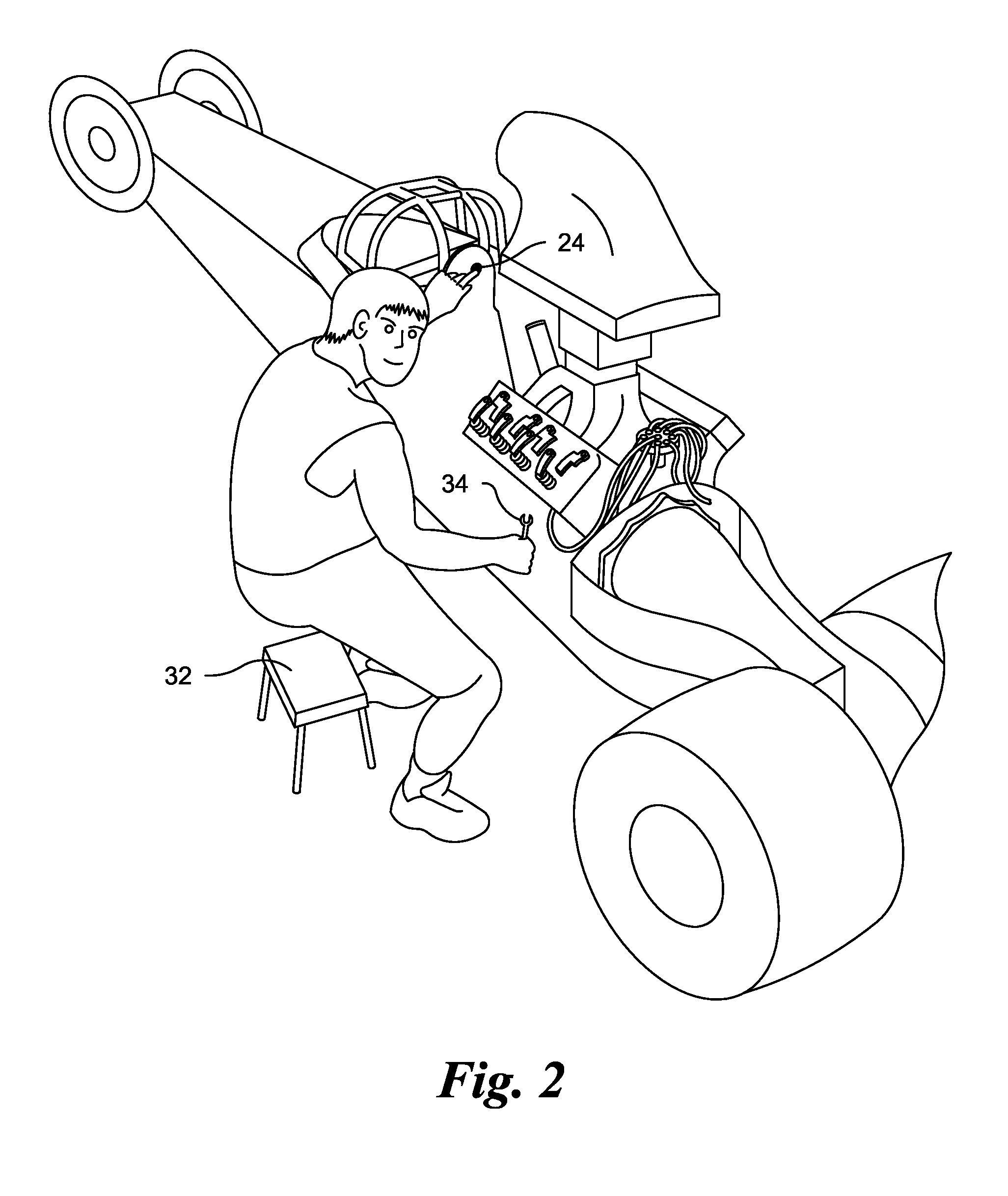
[0028]As mentioned above, the engine is mounted to keep the center of gravity of the vehicle as low as possible, and the valve train is therefore between about two and three feet above the roadway. A racing crew member 30, seated on a stool 32, is shown adjusting the rearmost intake valve on the left side of the engine using a wrench 34 in his right hand, while ...


PUM


Abstract

In a drag racing vehicle, especially one utilizing a V-block engine, valve gap measurement and adjustment, valve spring force measurement, and the like are carried out with the aid of a foot-operated switch removably connectible to a circuit that carries battery current to the vehicle's starter motor. The foot switch is provided with a cable allowing it to be positioned in either side of the vehicle. Operation of the foot switch effects rotation of the engine crankshaft and camshaft through a small angle so that each valve can be brought to a fully closed condition for measurement or adjustment.

Description

CROSS REFERENCE TO RELATED APPLICATIONS[0001]This application claims the benefit of the priority of U.S. Provisional Patent Application No. 61 / 512,734, filed Jul. 28, 2011. U.S. Patent Application No. 61 / 512,734 is hereby incorporated herein by reference in its entirety.FIELD OF THE INVENTION[0002]This invention relates to the tuning of internal combustion engines, and is especially applicable to high performance engines used in automobile racing. The invention relates more particularly to an improved method and apparatus for “bumping” an engine, i.e., rotating the engine crankshaft through small angles in the process of measuring and adjusting valve lash, checking spring pressure, etc.BACKGROUND OF THE INVENTION[0003]In automobile racing using a high performance engine having its camshaft inside the engine block, it is important for optimum performance to maintain prescribed clearances between the valves and the rocker arms when the valves are closed. In dragster racing, before a r...

Claims


Application Information

Patent Timeline
IPC IPC(8): F01L1/00F02N11/08
CPCF01L1/20F02N11/003F02N11/0803F01L1/146G01B5/0032F01L2800/17
Inventor CICCARONE, THOMAS E.
Owner CICCARONE THOMAS E
Learn More