Steering wheel

a technology of steering wheel and horn switch, which is applied in the direction of mechanical control devices, pedestrian/occupant safety arrangements, instruments, etc., can solve the problems of horn switch not being operated horn switch damage, etc., to reduce the load applied to and wear on the elastic member, and prolong the life of the dynamic damper. , the effect of reducing the weight of the insulator

Inactive Publication Date: 2013-01-31
JOYSON SAFETY SYST JAPAN KK
View PDF14 Cites 33 Cited by
  • Summary
  • Abstract
  • Description
  • Claims
  • Application Information

AI Technical Summary

Benefits of technology

[0019]The lightening holes formed in the wall surface portion can minimize an increase in the weight of the insulator due to formation of the wall surface portion.
[0020]With the elastic member and the protector disposed in the insulator, a dynamic damper can be configured so that the natural frequency of the pad as a mass body is adjusted to cancel and damp a vibration transferred from the main body by the sympathetic vibration of the pad. Additionally, a load applied to and wear on the elastic member can be reduced, thereby allowing the life of the dynamic damper to be extended. Furthermore, with the linear protrusions formed on the surface of the insulator in contact with the elastic member, a frictional force can be effectively generated between the insulator and the elastic member and the magnitude of the frictional force generated between the insulator and the elastic member can be easily adjusted. Thus, the frequency of the dynamic damper can be easily adjusted.
[0021]By dividing the insulator into the first insulator and the second insulator, the insulator can be easily assembled. In addition, a load applied to the elastic member can be reduced also by bringing the leg portion of the second insulator in contact with the stopper.
[0022]By providing a sufficient gap between the first horn plate and the stopper, the insulator with a damping function, the thickness of which tends to increase, to be disposed between the first horn plate and the stopper can be mounted in the gap. By forming the synthetic-resin insulator formed to have the thickness with which most of the gap is occupied, the insulator with a damping function can be replaced with that without a damping function without changing the shapes and the like of the surrounding components (for example, the shape of the fixing hole of the horn plate, the shape and tightening amount of the guide pin, the shape and spring constant of the coil spring, etc.). Thus, the number of components and man-hours for management can be reduced, thereby allowing the cost to be reduced.
[0023]By forming the gap in advance to fit the shape of the insulator with a damping function to be mounted therein, the insulator according to the present invention can be easily replaced with that with a damping function.
[0024]By forming the insulator to have an external shape substantially the same as that of the insulator with a damping function, the same structure as that for the insulator with a damping function can be used for securing the insulator to the horn plate, thus facilitating replacement of the insulator.

Problems solved by technology

Thus, it is difficult to recognize a state in which the excess portion of the harness is housed in the space.
Thus, in the case where the moving parts (the stoppers or the heads of the connection bolts) of the horn switches exist in this space, there is a possibility of the harness getting caught in the gap between the stopper (the head of the connection bolt) and the insulator, the gap being formed when the horn is sounded.
When the harness gets caught in this gap, the harness would be damaged or the horn switch could not be operated.

Method used


Image

  • Steering wheel
  • Steering wheel
  • Steering wheel

Examples


first embodiment

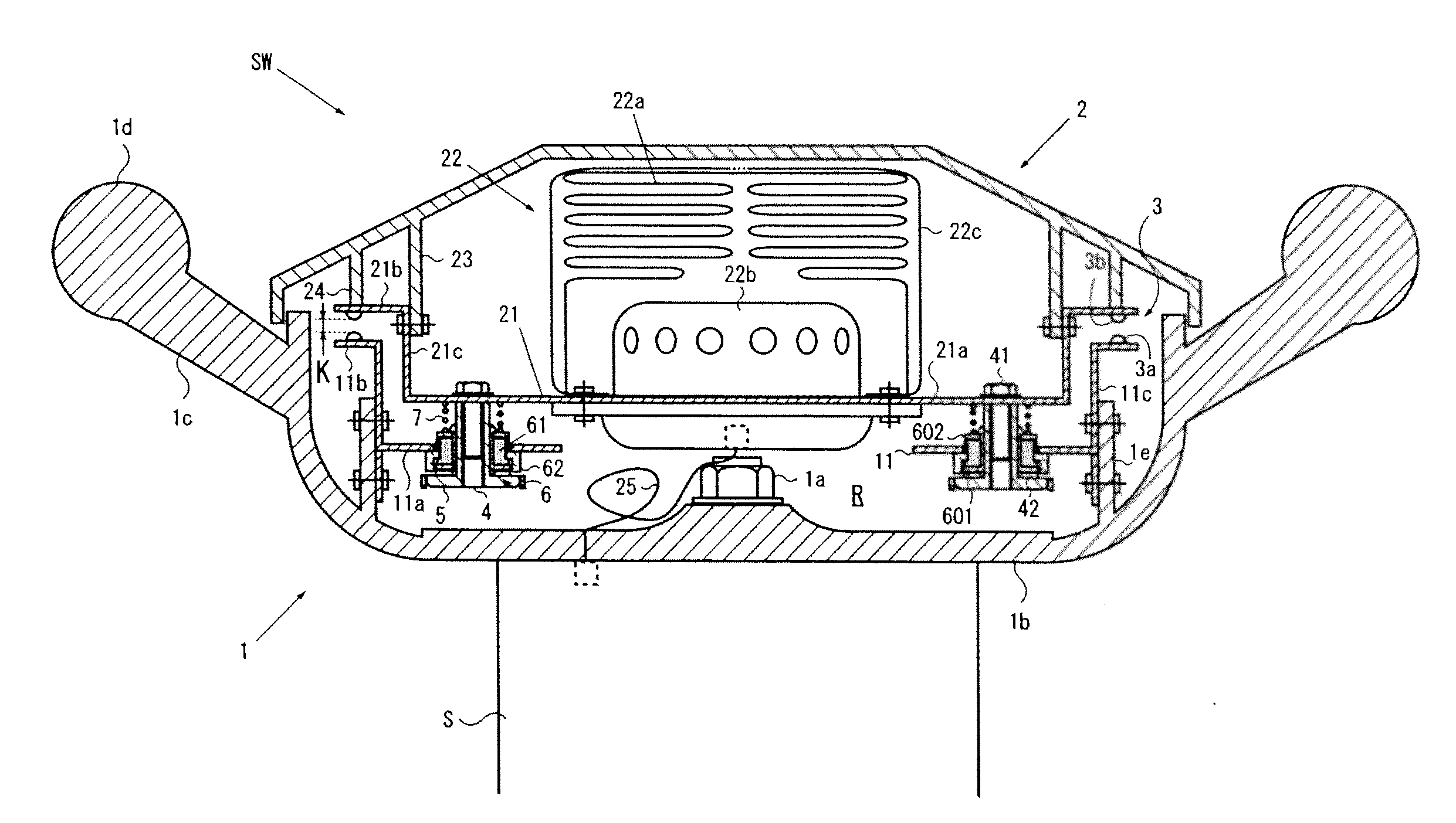
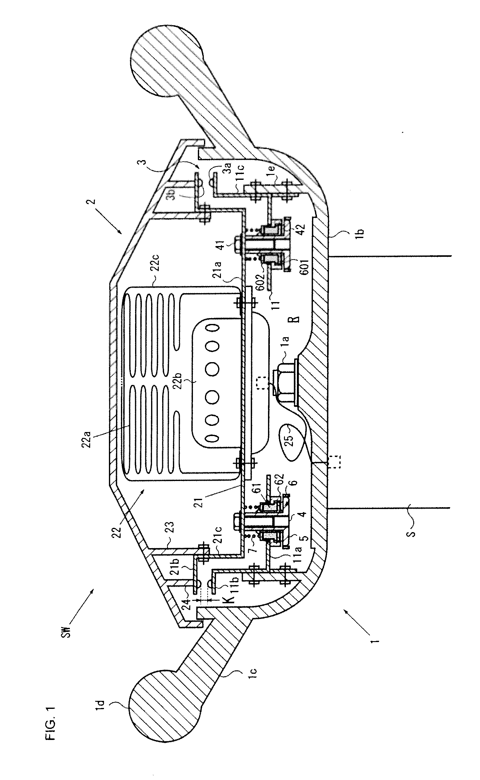
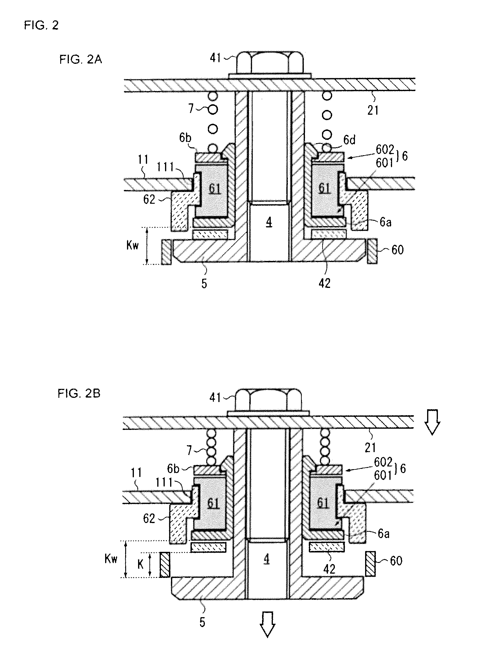
[0034]Embodiments of the present invention will be described below with reference to FIGS. 1-9. FIG. 1 shows a sectional view of a steering wheel according to the present invention. FIG. 2 shows enlarged views of a support structure of one of horn switches shown in FIG. 1, wherein FIG. 2A shows a normal state, and FIG. 2B shows a state where a horn is sounded. FIG. 3 shows detailed views of one of first insulators shown in FIG. 1, wherein FIG. 3A shows a plan view, FIG. 3B shows a rear view, FIG. 3C shows a view in the direction of arrow C in FIG. 3A, and FIG. 3D shows a sectional view taken along line D-D in FIG. 3A. FIG. 4 shows detailed views of one of second insulators shown in FIG. 1, wherein FIG. 4A shows a plan view, FIG. 4B shows a rear view, and FIG. 4C shows a view in the direction of arrow C in FIG. 4A. FIG. 5 shows detailed views of one of elastic members shown in FIG. 1, wherein FIG. 5A shows a plan view, FIG. 5B shows a rear view, and FIG. 5C shows a view in the direct...

second embodiment

[0085]In the steering wheel SW shown in FIG. 8A, a gap G having a size at least twice the thickness T of the first horn plate 11 is formed between the first horn plate 11 and each of the stoppers 5. Each insulator 6, the entirety of which is formed of synthetic resin as an integral unit, has a thickness Ti with which most of the gap G is occupied.

[0086]The thickness Ti of the insulator 6 is set to be a thickness that occupies, for example, 60 to 100% of the gap G. This occupying ratio of the thickness Ti to the gap G can be arbitrarily set in accordance with the size of the gap G and the presence or absence the washer 42. For example, when the size of the gap G is 3 mm, the thickness Tw of the washer 42 is 1 mm, and the thickness Ti of the insulator 6 is 2 mm, the occupying ratio is 66%. When the size of the gap G is 5 mm, the thickness Tw of the washer 42 is 1 mm, and the thickness Ti of the insulator 6 is 4 mm, the occupying ratio is 80%. When the size of the gap G is 5 mm, the t...


PUM


Abstract

Provided is a steering wheel in which, even in the case where a moving part of a horn switch exists in a space formed between a pad and a main body, harness can be prevented from getting caught in a gap. The steering wheel includes a first horn plate secured to the main body, a second horn plate secured to the pad, guide pins arranged vertically on the second horn plate and inserted through openings of the first horn plate, flange-shaped stoppers formed on the guide pins, an insulators disposed so as to be slidable along the guide pins, and coil springs that urge the insulators toward the stoppers. The insulator covers an outer periphery of the stopper and has a wall surface portion, the height of which is substantially equal to an offset distance between a fixed contact and a moving contact.

Description

CROSS-REFERENCE TO RELATED APPLICATION [0001]This application claims priority under 35 U.S.C. §119 to Japanese Patent Application No. JP2011-164308 filed on Jul. 27, 2011, the entire content of which is hereby incorporated herein by reference in its entirety.FIELD OF THE INVENTION [0002]The present invention relates to a steering wheel installed in a vehicle such as an automobile, and in particular, relates to a steering wheel comprising an insulator disposed in a sliding portion of a horn switch.BACKGROUND OF THE INVENTION[0003]Steering wheels used to steer vehicles such as automobiles including a main body attached to a steering shaft for converting rotational operation into steering operation and a pad disposed in a substantially central portion of the main body is known (for example, see Japanese Unexamined Patent Application Publication Nos. 2003-154943 and 2011-110941). In the steering wheel, the pad is attached to the main body such that the pad is movable in the axial direct...

Claims


Application Information

Patent Timeline
Patent Type & Authority Applications(United States)
IPC IPC(8): B60R21/203B62D1/10
CPCY10T74/20834B60Q5/003B60R21/2037
Inventor ONOHARA, KEISUKE
Owner JOYSON SAFETY SYST JAPAN KK
Why Eureka
Try Eureka