

Method and apparatus for aligning phased array antenna, and phased array antenna
a technology of phased array antennas and antennas, applied in the field of communication, can solve the problems of inability to meet the needs of modern communication, laborious maintenance of antennas, and deterioration of communication quality, and achieve the effect of increasing the working efficiency of phased array antennas and high degree of automation
- Summary
- Abstract
- Description
- Claims
- Application Information
AI Technical Summary
Benefits of technology
Problems solved by technology
Method used
Image

Examples
embodiment 1
[0034]A phased array antenna (Phased array antenna) is an antenna that uses an electronic control method to change a phase of a radiation unit in an array, so as to make a beam scan the space as required. The antenna changes the shape of a pattern by controlling a feed phase of the radiation unit in the array antenna. By controlling the phase, a direction of a maximum value of the pattern of the antenna may be changed, so as to achieve the objective of beam scanning. A pattern illustrates directional characteristics of antenna transmitting (or receiving) energy. Characteristics of antenna transmitting energy are shown by a transmission pattern, and characteristics of antenna receiving energy are shown by a reception pattern. Generally speaking, a transmission pattern of an antenna coincides with a reception pattern of the antenna with respect to the shape. A scan speed of a beam of a phased array antenna is high, a feed phase is controlled by a computer, and the rate of change of th...
embodiment 2
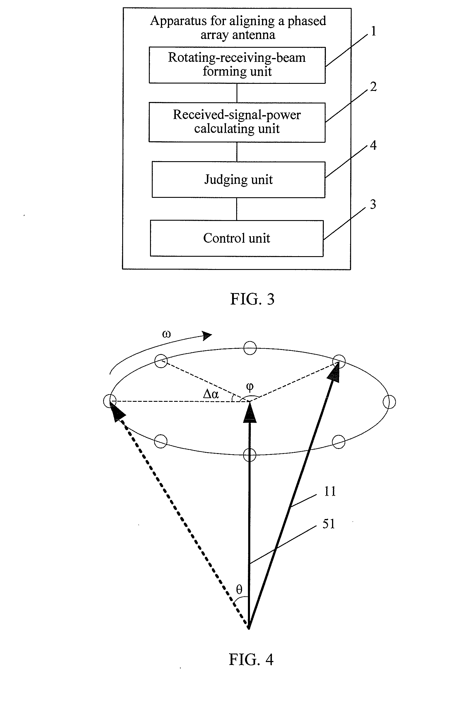
[0051]The embodiment provides a method for aligning a phased array antenna, and as shown in FIG. 4 and FIG. 5, the method includes:
[0052]Step 201: A direction of a transmitting / receiving beam is initialized to be a normal direction of a plane where a phased array antenna is located. Here, the direction of a transmitting / receiving beam 51 is the direction of the phased array antenna.
[0053]Step 202: A direction of a rotating receiving beam 11 is initialized to be (θ, φ), where,
[0054]θ represents an included angle between the rotating receiving beam 11 and the transmitting / receiving beam 51, that is, a deflection angle relative to the transmitting / receiving beam 51, and in the embodiment, θ is greater than 0° and a preferred value range is 011 rotates from an initial state to the present, φ=ω×t, and t represents total time the rotating receiving beam 11 rotates.
[0055]When the included angle θ between the receiving beam and the local transmitting / receiving beam is a determined value, if...
embodiment 3
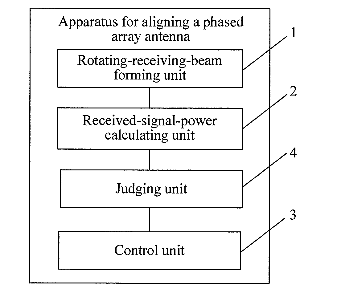
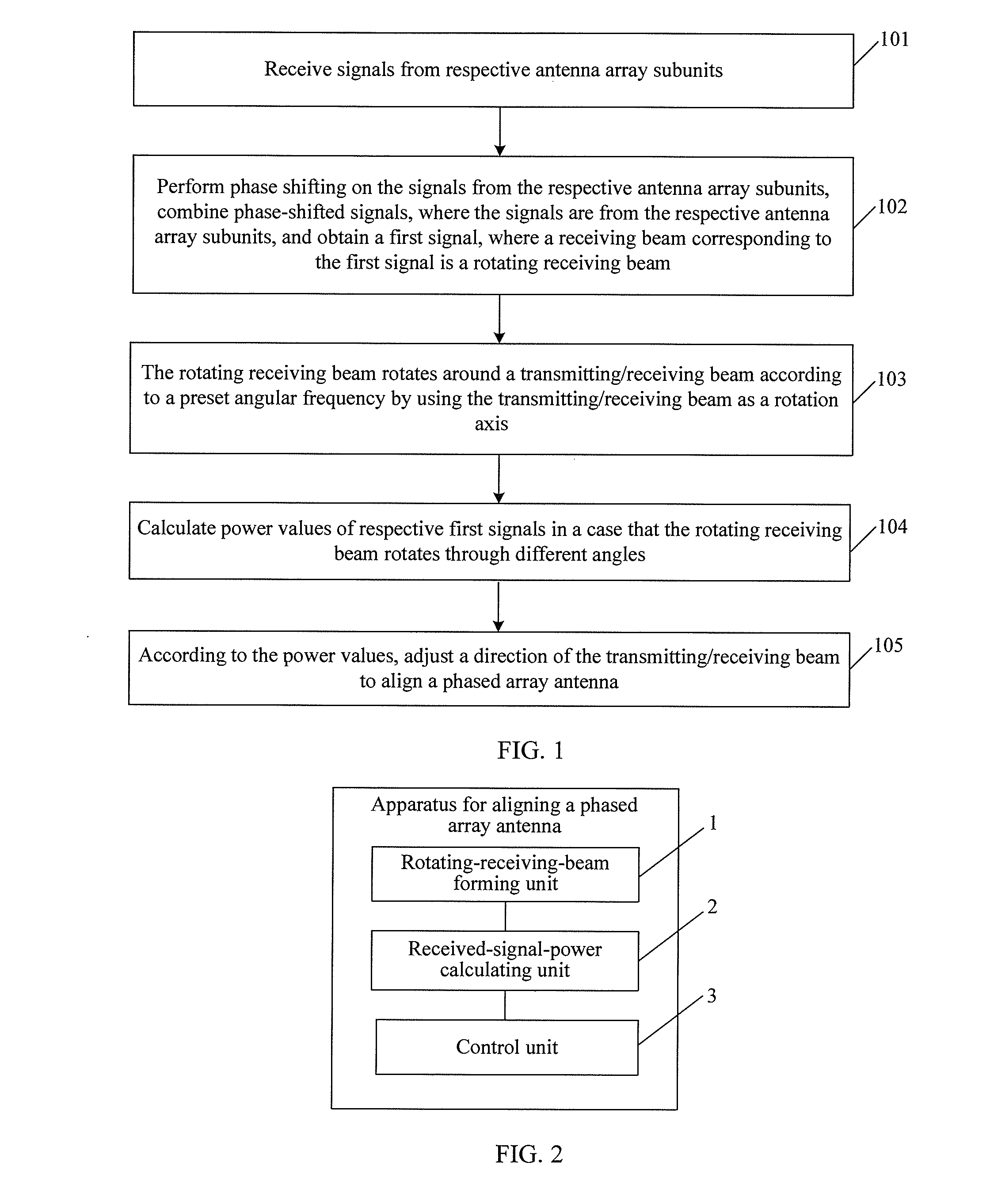
[0071]The embodiment provides an apparatus for aligning a phased array antenna, and as shown in FIG. 2 and FIG. 3, the apparatus includes a rotating-receiving-beam forming unit 1, a received-signal-power calculating unit 2 and a control unit 3.
[0072]The rotating-receiving-beam forming unit 1 is configured to receive signals from respective antenna array subunits; perform phase shifting on the signals from the respective antenna array subunits, combine phase-shifted signals, where the signals are from the respective antenna array subunits, and obtain a first signal. A receiving beam corresponding to the first signal is a rotating receiving beam.
[0073]The rotating receiving beam rotates around a transmitting / receiving beam according to a preset angular frequency by using the transmitting / receiving beam as a rotation axis.
[0074]As shown in FIG. 8, the rotating-receiving-beam forming unit according to the embodiment includes: multiple phase shifters 12, a power divider 13 and a beam dir...
PUM
 Abstract
Description
Claims
Application Information