High data rate magnetic writer design

a magnetic writer and data rate technology, applied in the field of magnetic disk recording data, can solve the problems of accidental erasure of data, not all soft magnetic materials have an ms value, etc., and achieve the effect of high damping constant, high damping, and significant increase of damping constan

Active Publication Date: 2013-01-31
HEADWAY TECH INC
View PDF0 Cites 15 Cited by
  • Summary
  • Abstract
  • Description
  • Claims
  • Application Information

AI Technical Summary

Benefits of technology

[0009]It has been an object of at least one embodiment of the present invention to describe a high data rate magnetic writer
[0010]Another object of at least one embodiment of the present invention has been to present a process for the manufacture of said high data rate magnetic writer.
[0011]Still another object of at least one embodiment of the present invention has been to describe the composition of several key sub-structures within said high data rate magnetic writer.
[0012]These objects have been achieved by utilizing magnetic materials with high damping constant as part or all of the writer's magnetic sub-structure. These materials are high moment Co, Fe, Ni alloys doped with a small percentage of rare earth and / or 3d-5d transition metals that will increase the damping constant significantly.
[0013]An important feature of the invention is the provision of a stitched pole tip that works in conjunction with the main pole. The material composition of each of these two sub-structures is slightly different; one sub-structure is optimized for high magnetic damping while the other sub-structure is optimized for high saturation magnetization. This arrangement results in a device having both a high damping constant as well as a high saturation magnetization.

Problems solved by technology

Another issue facing today's high density writers is the accidental erasure of data due to the remnant magnetization of the write pole.
However, not all soft magnetic materials have an Ms value that is large enough to provide a high intensity writing field.

Method used


Image

  • High data rate magnetic writer design
  • High data rate magnetic writer design
  • High data rate magnetic writer design

Examples


first embodiment

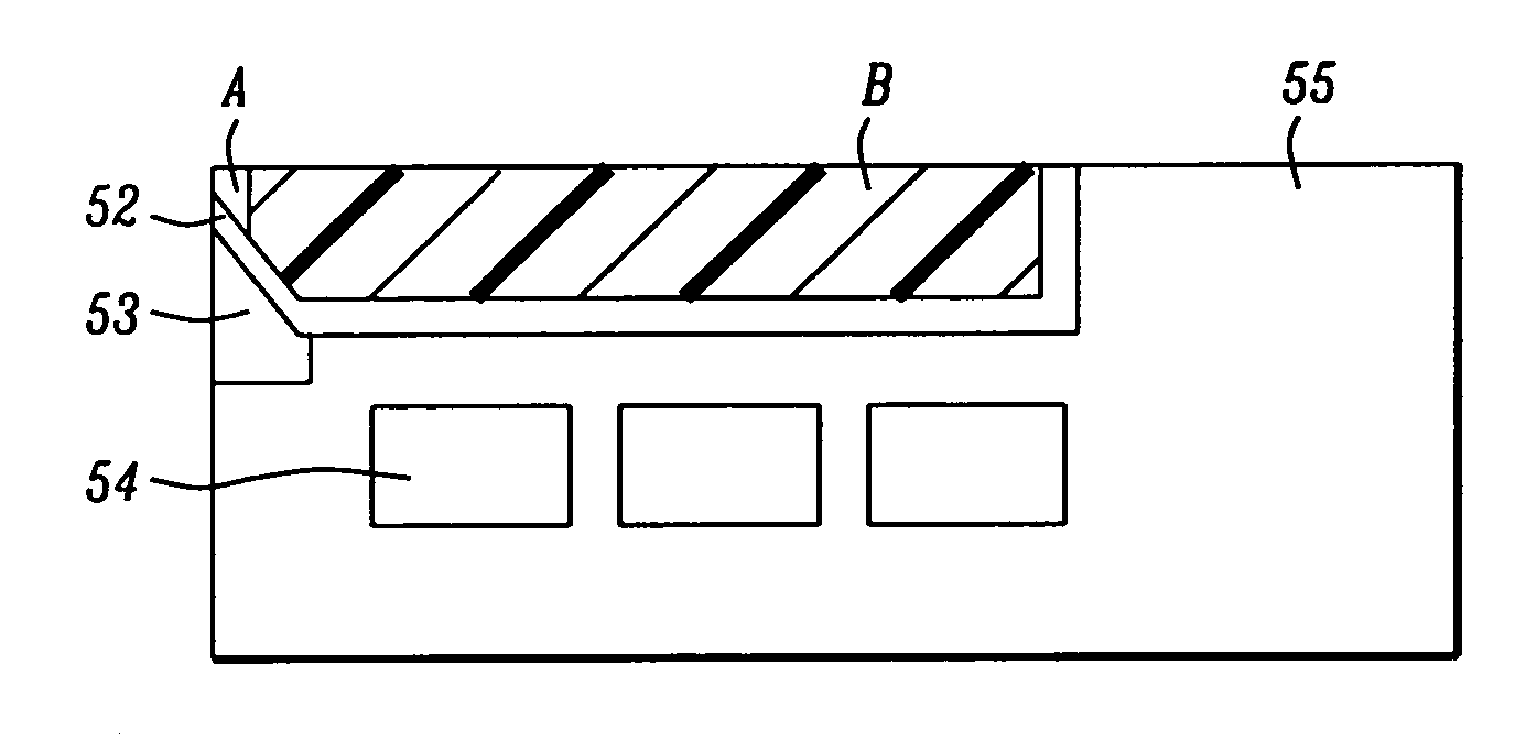
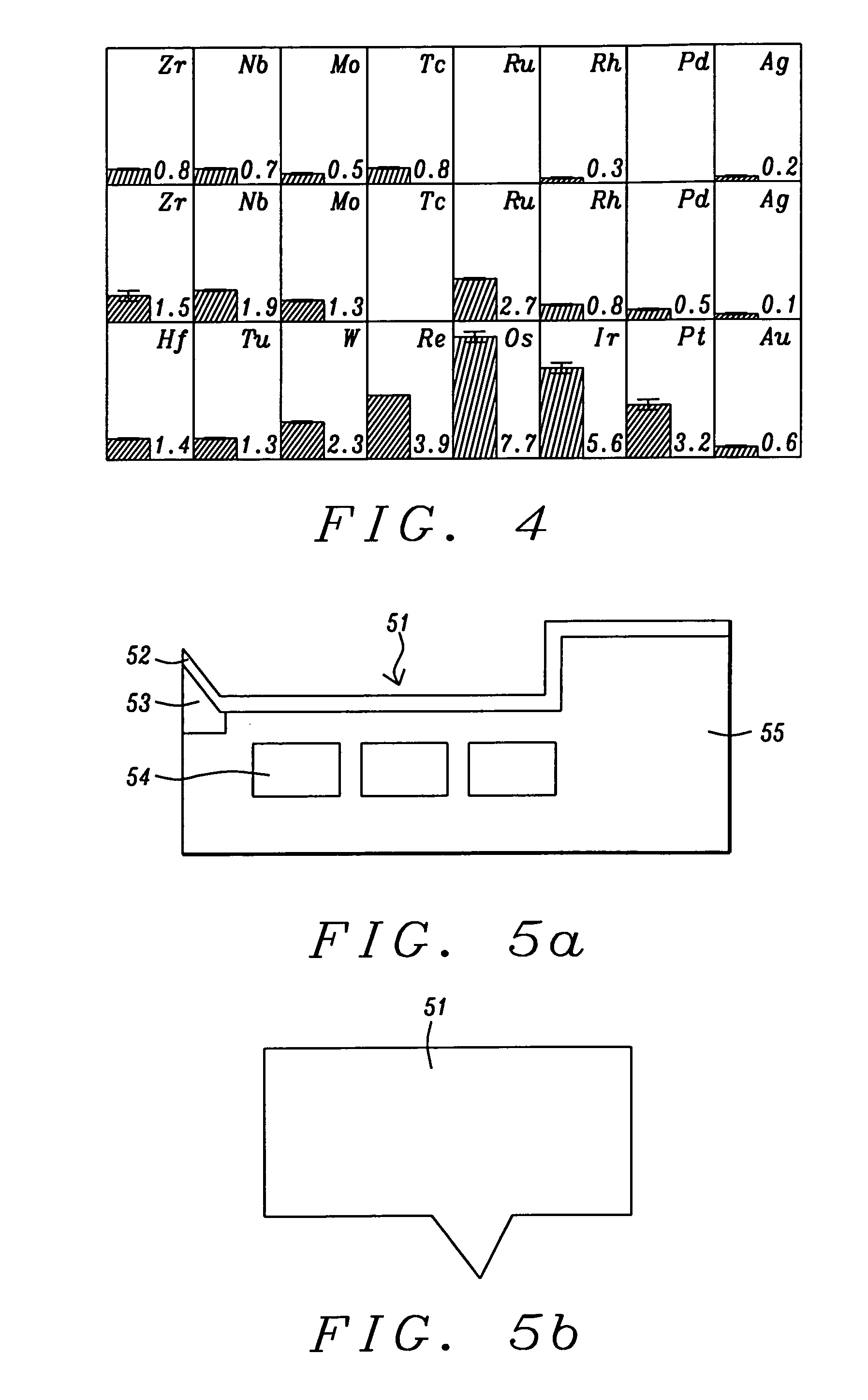
[0024]Referring now to FIG. 5a, we show there the starting point for the manufacture of the invention. This initial structure includes lower field coil 54 that has been embedded within non-magnetic dielectric 55. Cavity 51 has been formed in the top surface of 55 and its internal walls have been coated with layer 52 suitable for use as the write gap portion of the final structure. Note that one of these internal walls is not vertically oriented relative to the floor of cavity 51 but, rather, slopes upwards at an angle of about 30 degrees relative to, and away from, the floor. Note, too, the presence of leading shield 53 located between layer 55 and the underside of layer 52.

[0025]FIG. 5b is a bird's eye view of FIG. 5a from a point located a short distance above 5a.

[0026]Next, as illustrated in FIG. 6, photoresist layer 61 is laid down and patterned to form a mask that covers all of layer 52 except about half the sloping portion of 52 that was described above. Next, in a key feature...

second embodiment

[0032]In a second embodiment, the high-α material is used in other parts of the writer as well. The yoke for example. This is illustrated in FIG. 11 where only top yoke 111 is explicitly shown. However, the top and / or the bottom (B) sections of the yoke could also have been formed in the same way (i.e. with high-α material). Also shown in FIG. 11 are upper field coils 154 and background material 113 (such as Al2O3).

third embodiment

[0033]In a third embodiment, high-α material is used for some or all of the remaining parts of the writer structure, as shown in FIG. 7.


PUM

PropertyMeasurementUnit
angleaaaaaaaaaa
thicknessaaaaaaaaaa
angleaaaaaaaaaa

Abstract

A high speed magnetic data writer containing a stitched pole tip that works in conjunction with the main pole is disclosed, together with a process for their manufacture. The material composition of each of these two sub-structures is slightly different; one sub-structure is optimized for high magnetic damping while the other sub-structure is optimized for high saturation magnetization.

Description

FIELD OF THE INVENTION[0001]The invention relates to recording data on magnetic disks, with particular reference to the design and manufacture of devices capable of recording at rates in the gigabits per second range.BACKGROUND OF THE INVENTION[0002]For today's high density magnetic recording, the recorded bits per inch (BPI) and the data rate for writing have both either already entered, or are rapidly approaching, the Giga range. It is essential that this increase in the data rate capability of writers not be accompanied by an increase in the bit error rate (BER).[0003]To enhance the data rate of a writer, its frequency response to the writing current has to be improved. During the writing process, magnetization will follow the Landau-Lifshitz-Gilbert equation:Mt=-γM×Heff+αMM×Mtwhere M is the magnetization, γ is the gyromagnetic coefficient, Heff is the field, including the applied field, the demagnetization field, and the anisotropic field. α is the Gilbert damping constant. The ...

Claims


Application Information

Patent Timeline
Patent Type & Authority Applications(United States)
IPC IPC(8): G11B5/187C25D5/02
CPCC25D5/022G11B5/3163G11B5/3116
Inventor MIN, TAIGUAN, LIJIELI, MINLEE, JIUN-TING
Owner HEADWAY TECH INC
Why Eureka
Try Eureka