Light collecting and emitting apparatus, method, and applications

Active Publication Date: 2013-01-31
UNIVERSITY OF ROCHESTER
View PDF1 Cites 14 Cited by
  • Summary
  • Abstract
  • Description
  • Claims
  • Application Information

AI Technical Summary

Benefits of technology

[0018]The combination of a light injection element and a bypass element of any type or form described herein will be referred to herein as a “dimple”. A light guide including a guide layer with one or more di

Problems solved by technology

By concentrating solar energy with optics, less photovoltaic (PV) material is used, reducing cost, since PVs are expensive and energy-intensive to produce compared with optical components.
The presence of the light injection elements res

Method used


Image

  • Light collecting and emitting apparatus, method, and applications
  • Light collecting and emitting apparatus, method, and applications
  • Light collecting and emitting apparatus, method, and applications

Examples


Embodiment Construction

[0082]Reference will now be made in detail to the present exemplary embodiments of the invention, examples of which are illustrated in the accompanying drawings.

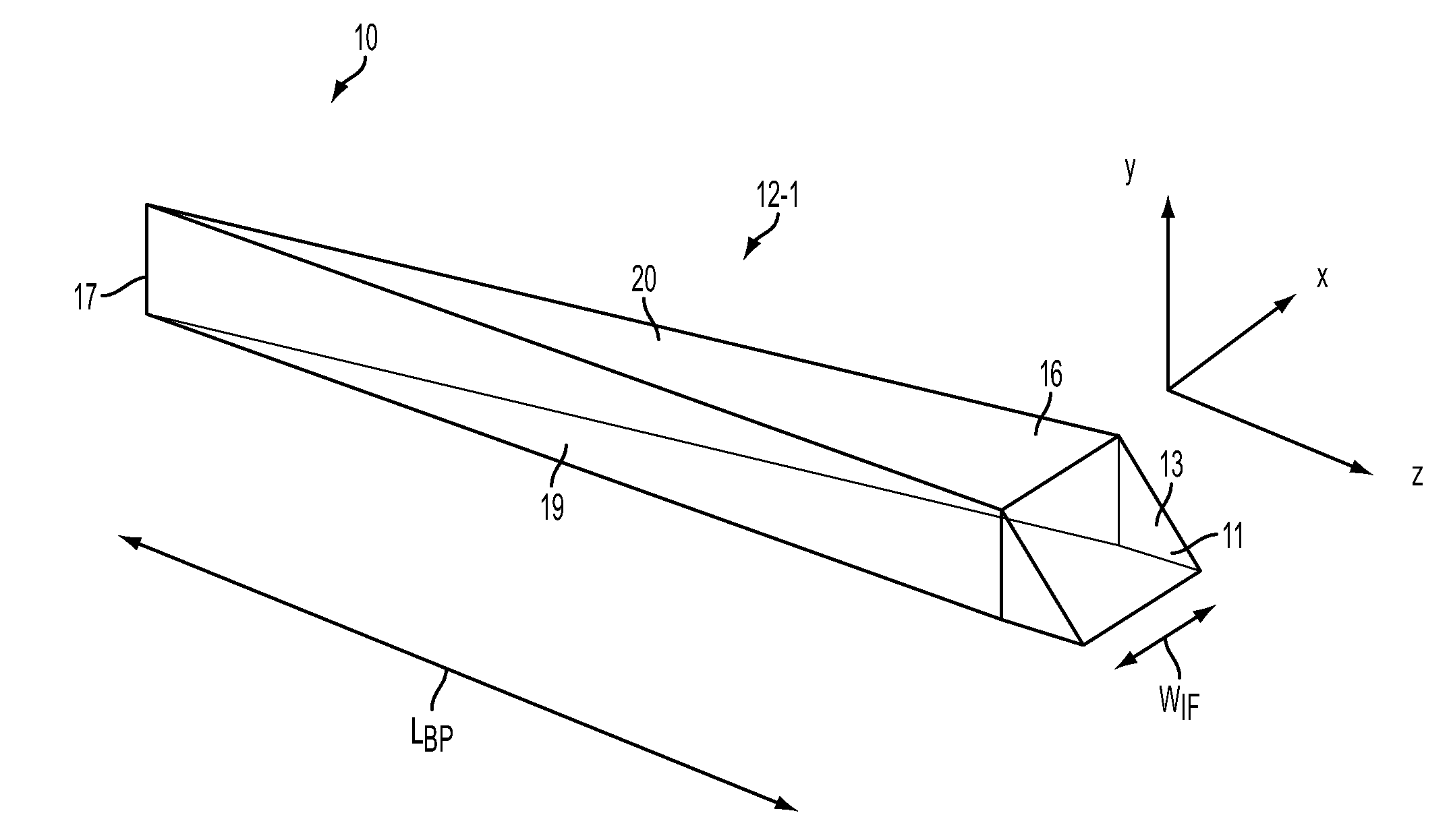
[0083]A ‘dimple’ according to a representative aspect of the invention is shown in FIG. 3, and is designated by reference numeral 10. As used herein in accordance with a non-limiting embodiment of the invention, the term ‘dimple’ refers to a structural component of a planar light guide. As illustrated in FIGS. 3A and 4B, the dimple 10 is composed of two parts: a light injection element 11 and a light bypass element 12. Each injection element in the light guide is located to receive focused or near-focus light from a respective primary light concentrator element (e.g., lenslet) as described in greater detail below. In the instant aspect, the injection element acts to redirect light from a direction generally normal to the light guide (−y direction in FIG. 1) to a propagation direction in the light guide (z-direction) towards ...


PUM


Abstract

A light guide apparatus includes a light guide layer and an injection layer further including light injection elements and respective light bypass elements disposed optically upstream of the light injection elements. The light injection elements and/or the bypass elements may take the form of air prisms. There is an axial index of refraction variation between the light guide layer and the injection layer. The axial index of refraction variation may be discrete or may be an axial gradient index variation.

Description

CROSS-REFERENCE TO RELATED APPLICATIONS[0001]This application is a continuation-in-part application of U.S. Ser. No. 13 / 108,225 filed on May 16, 2011, and a continuation-in-part application of U.S. Ser. No. 12 / 490,417 filed on Jun. 24, 2009, the subject matters of which are incorporated by reference herein in their entireties, and claims priority to both.GOVERNMENT SPONSORSHIP[0002]This invention was made with government support under DARPA-MGRIN Phase 1 Agreement No. HR0011-10C-0111. The government has certain rights in the invention.BACKGROUND OF THE INVENTION[0003]1. Field of the Invention[0004]Embodiments of the invention relate generally to the field of optical light guides and, more particularly, to non-imaging, light collecting and emitting apparatus, methods, and applications. Even more particularly, embodiments of the invention relate to a light collection and light guide apparatus for use in a concentrated photo-voltaic (CPV) solar energy system, and other applications.[00...

Claims


Application Information

Patent Timeline
IPC IPC(8): G02B6/10G02B6/32
CPCY02E10/52H01L31/0547G02B6/0036G02B6/0018
Inventor MOORE, DUNCAN T.SCHMIDT, GREG R.BROWN, MICHAEL
Owner UNIVERSITY OF ROCHESTER
Why Eureka
Try Eureka