
Movable solar heat collection device

A technology of solar heat collection and solar heat collector panels, which is applied in mobile/directional solar heat collectors, solar heat collectors, solar heat collector controllers, etc., which can solve the problem of less concentrated solar energy and lower sunlight utilization rate, etc. problem, to achieve the effect of small reflection loss, enhanced practicability and controllability, and improved conversion rate

Inactive Publication Date: 2020-02-11
张俊霞
View PDF5 Cites 0 Cited by
  • Summary
  • Abstract
  • Description
  • Claims
  • Application Information

AI Technical Summary

Problems solved by technology

[0003] In order to overcome the above-mentioned shortcoming of the prior art, the object of the present invention is to provide a kind of movable solar heat collecting device, to solve the problem that the existing solar heat collecting cover reduces the utilization of sunlight due to the fact that the fixed position of the solar heat collecting cover causes less solar energy to be collected. rate technical issues

Method used

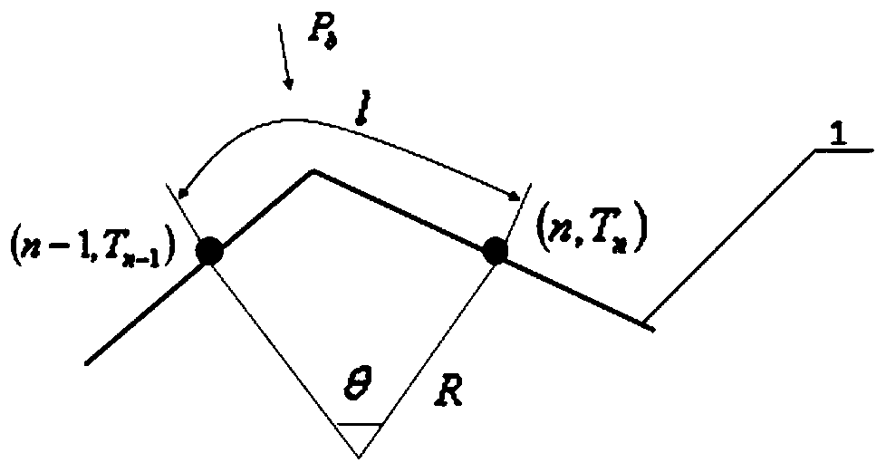

Image

  • Movable solar heat collection device
  • Movable solar heat collection device
  • Movable solar heat collection device

Examples


Embodiment 1

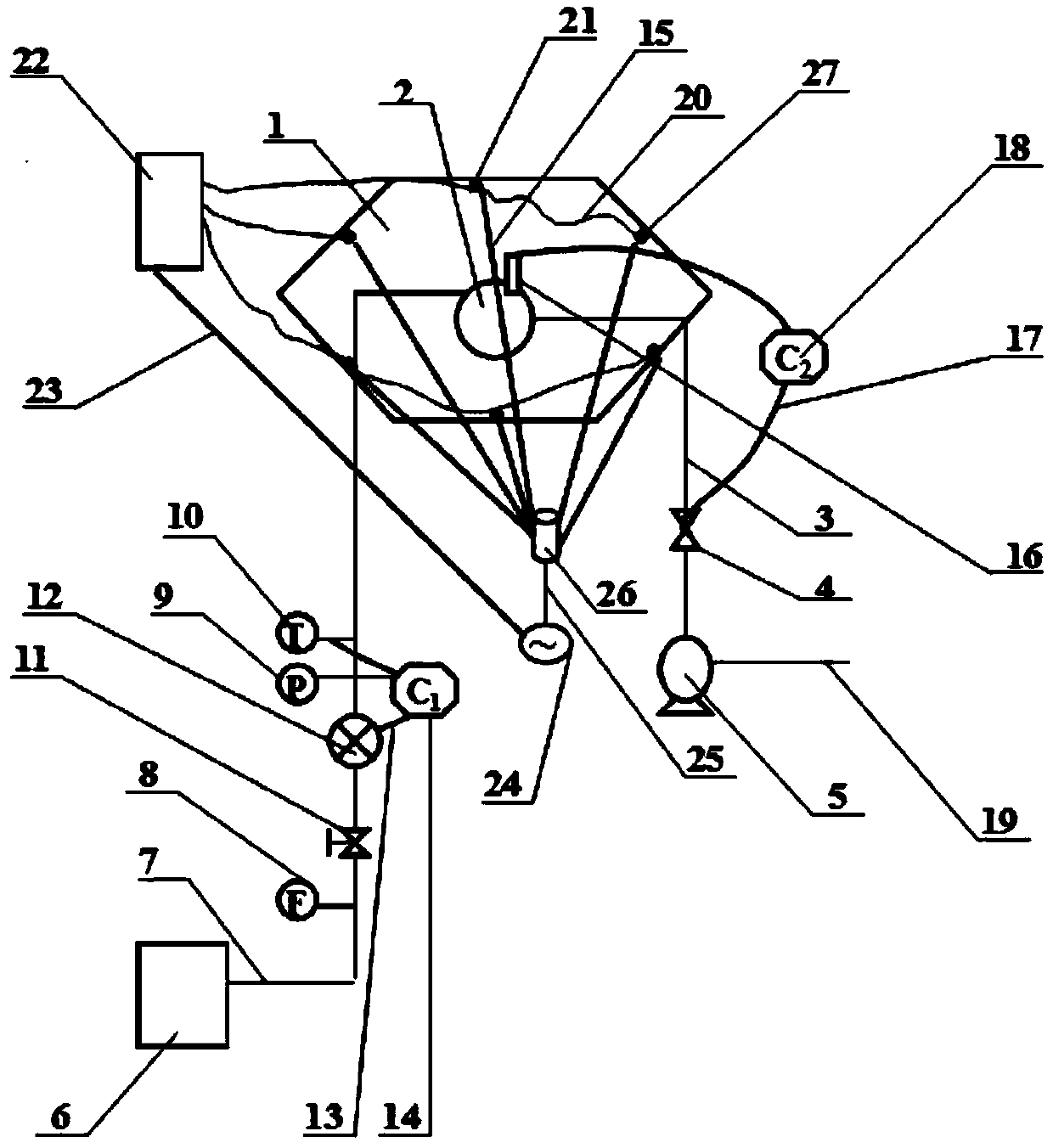
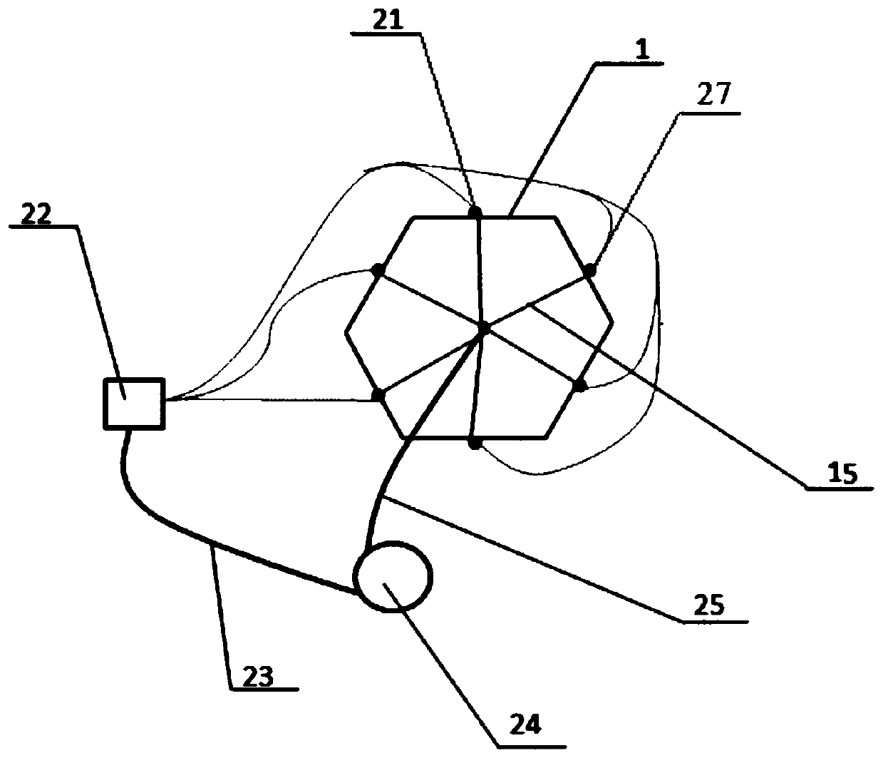
[0031] see figure 1 , a movable solar heat collection device, including a solar heat collection plate 1 and a concentrator tube 2, and six solar heat collector plates 1 are uniformly arranged on the top of the concentrator tube 2 along the circumferential direction with the concentrator tube 2 as the center A regular hexahedron heat collecting cover 20, the solar heat collecting plate 1 is connected with a solar heat collecting control system capable of controlling the direction of rotation and the angle of rotation of the solar heat collecting plate 1 so that it can collect solar energy from multiple angles, such as image 3 As shown, the solar heat collection control system includes a controller III22 installed on the regular hexahedron heat collecting cover 20, a motor 24 connected to the controller III 22 through a connection line 23, and electrically connected to the controller III 22 and installed in the solar collector. Six temperature sensors 21 on the thermal plate 1,...

Embodiment 2

[0033] This embodiment is except the following content, and all the other contents are identical with embodiment 1:

[0034] The condenser tube 2 is an airtight cylindrical structure made of stainless steel tubes, and the heat-absorbing paint layer is a black nickel paint layer.

Embodiment 3

[0036] This embodiment is except the following content, and all the other contents are identical with embodiment 1:

[0037] Eight solar heat collecting panels 1 are evenly arranged above the concentrating tube 2 along the circumferential direction with the concentrating tube 2 as the center to form a regular octahedral heat collecting cover 20; the concentrating tube 2 is a closed cylindrical structure processed by stainless steel tubes , The heat-absorbing paint layer is a black cobalt paint layer.

[0038]The working principle of the movable solar heat collecting device disclosed by the present invention is: a temperature sensor 21 is installed on each plate of the solar heat collecting plate 1, and since each plate of the solar heat collecting plate 1 is in a different position relative to sunlight, The received sunlight heat is different, causing the surface temperature of each board to be different. The temperature sensor 21 placed on the surface of each board senses thi...


PUM


Abstract

The invention discloses a movable solar heat collection device, and belongs to the technical field of solar heat utilization. The device comprises solar heat collecting plates and a light collecting barrel; the plurality of solar heat collecting plates are uniformly arranged on the upper portion of the light collecting barrel in the circumferential direction by taking the condenser barrel as the circle center to form a polyhedron heat collection cover; and the solar heat collecting plates are connected with a solar heat collecting system, and the solar control system integratedly controls a motor and a temperature sensor connected with the solar heat collecting plates through a controller to control the rotating direction and the rotating angle of the solar heat collecting plates, so thatthe solar heat collecting plates can receive sunlight to the greatest extent, the light collecting barrel is uniformly heated, and the utilization rate of sunlight is effectively improved. The deviceis simple in structure, small in occupied area, energy-saving and environment-friendly, and high in practicability.

Description

technical field [0001] The invention belongs to the technical field of solar heat utilization, and relates to a movable solar heat collecting device. Background technique [0002] At present, with the environmental pollution caused by fossil energy and the depletion of traditional energy sources, solar energy utilization technology has once again attracted the attention of domestic and foreign enterprises and researchers. Many applications. The current solar water heaters have a low conversion rate of solar energy, occupy a large area, and take a long time to heat, especially in winter or areas with short sunshine, the water temperature usually does not reach the required temperature, and it is inconvenient to use. The main reason is that the solar heat collecting cover is fixed at one position, and the sun rises from east to west, and there is very little time for sufficient sunlight to fall on the solar heat collecting cover. It is necessary to propose a movable solar hea...

Claims


Application Information

Patent Timeline
IPC IPC(8): F24S23/30F24S30/40F24S70/25F24S50/00F24S50/40F24S23/70F24S20/20
CPCF24S20/20F24S23/30F24S23/70F24S30/40F24S50/00F24S50/40F24S70/25F24S2030/11Y02E10/47
Inventor 张俊霞王泽华
Owner 张俊霞
Learn More