Electrical connection device

a technology of electric connection and connection plate, which is applied in the direction of electric connection structure association, connections, electric apparatus, etc., can solve the problems of increasing material use, and achieve the effect of reducing material use, reducing feed, and reducing the amount of required material

Inactive Publication Date: 2013-01-31
PHOENIX CONTACT GMBH & CO KG
View PDF7 Cites 13 Cited by
  • Summary
  • Abstract
  • Description
  • Claims
  • Application Information

AI Technical Summary

Benefits of technology

[0017]As part of the invention, it has been recognized that, in the production of a conductor through opening with a perforated collar which is closed in a ring shape, material also “afterflows” out of the lateral edge webs of the bus bar piece so that the material feed in the production of a, for example, 5 mm wide bus bar piece must be at least 8 mm. In contrast thereto, in the production of the connection device in accordance with the invention and the bus bar piece in accordance with the invention, most of the material for producing the contact section and the side walls does not flow out of the narrow edge webs, but only out of the region of the bus bar piece which adjoins the face side of the conductor through opening. In this way, the feed can be reduced in the production of the bus bar piece, as a result of which the material use per bus bar piece is reduced.
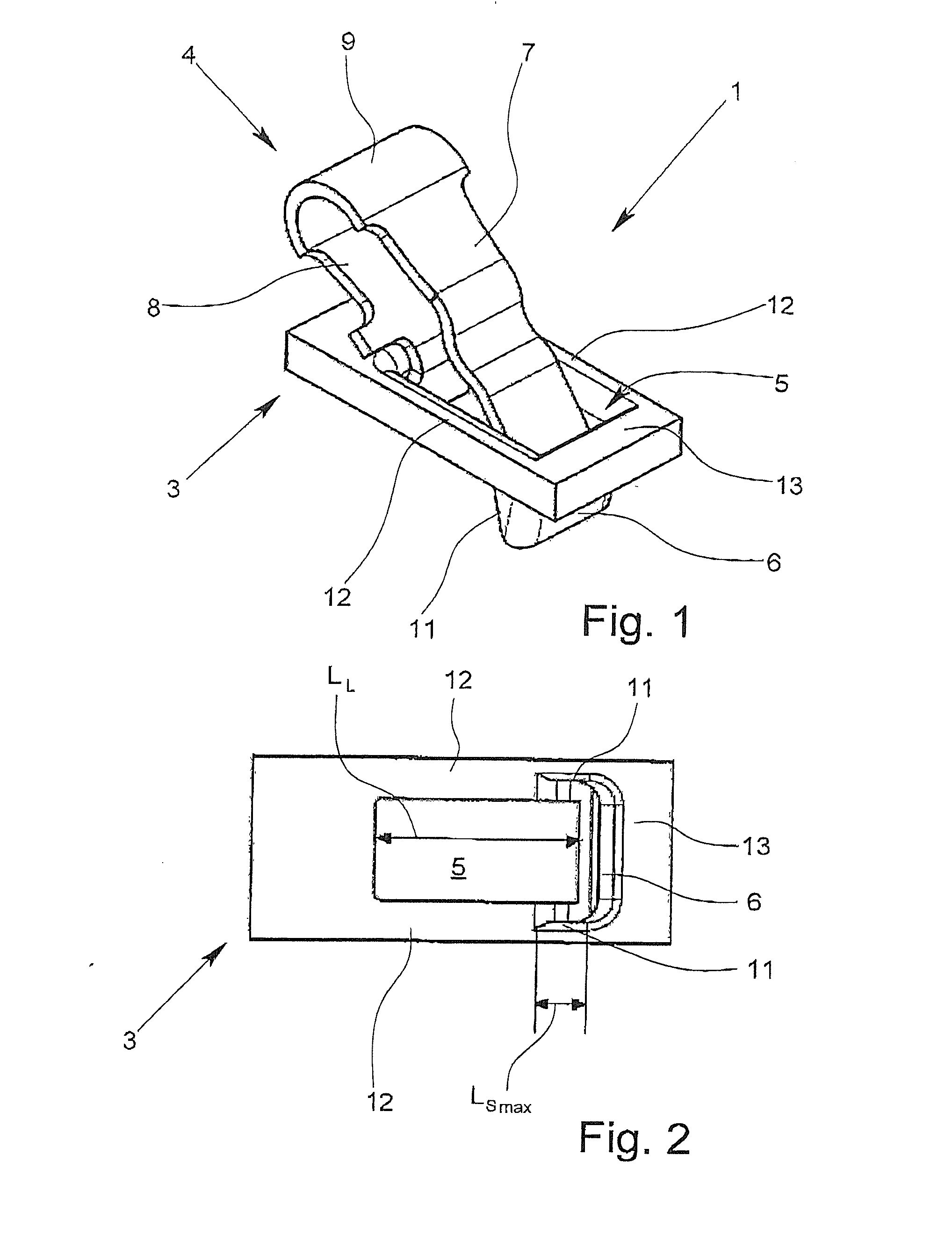
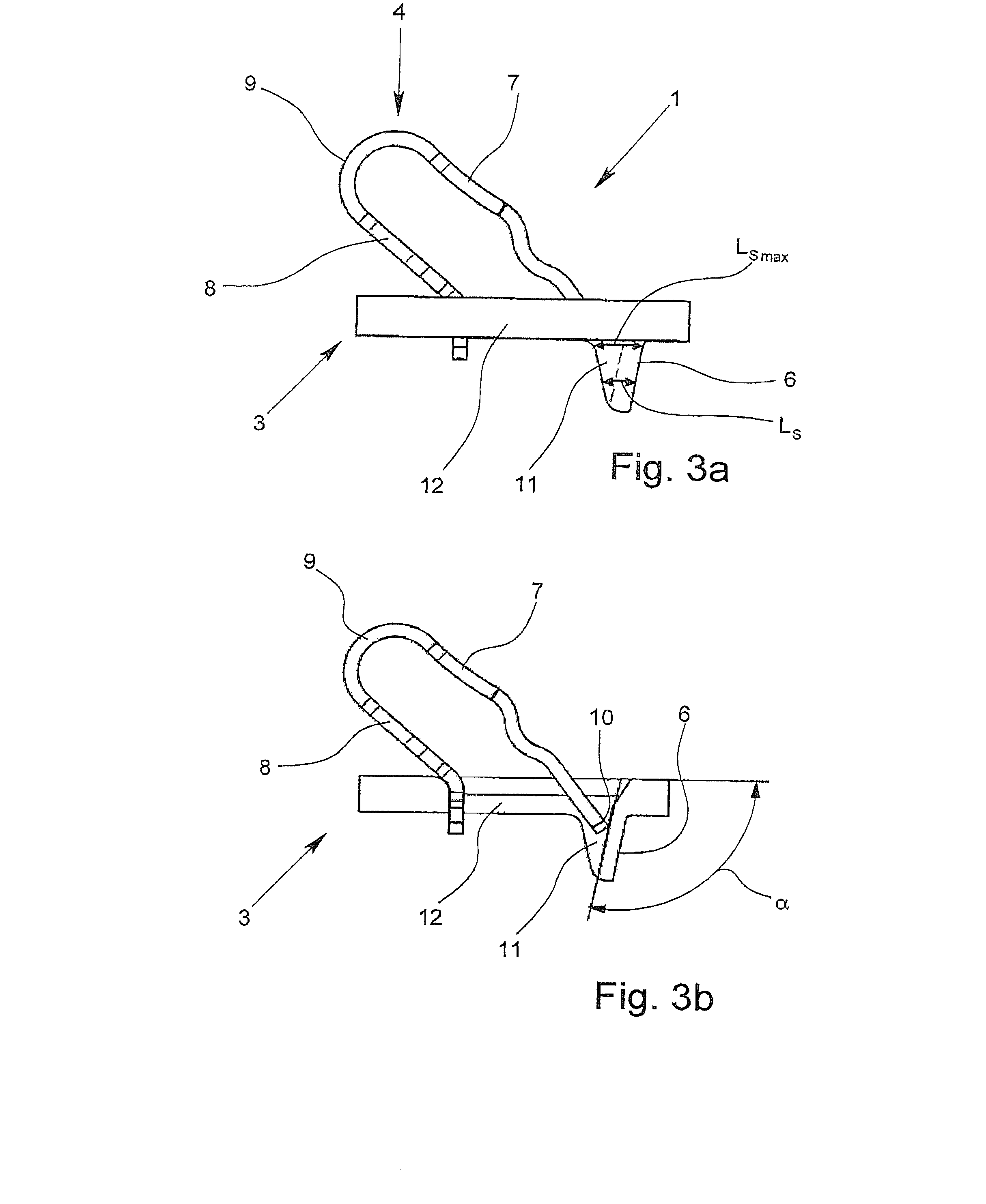
[0018]It was stated above that the side walls have a maximum extension in the longitudinal direction of the bus bar piece which is smaller than the longitudinal extension of the conductor through opening. Preferably, the maximum extension of the side walls is smaller than 50% of the longitudinal extension of the conductor through opening, as a result of which the “flow” of material out of the lateral edge webs is reduced, and thus, the required material use is further reduced. The maximum extension of the side walls should, however, be preferably at least 25%, especially at least 40% of the conductor cross section of the electrical conductor which is to be connected. This ensures that the conductor which is to be connected is adequately guided and cannot be forced out laterally on the contact section by the clamping leg. Moreover, the execution of the side walls increases the mechanical stability of the bus bar piece altogether and especially in the region of the spring force clamping connection, compared to a bus bar in which in the region of the conductor through opening only one contact surface is punched out and bent.
[0019]According to a first embodiment of both the electrical connection device in accordance with the invention and also the bus bar piece in accordance with the invention, the bus bar piece has only the above described contact section with the two side walls, while on the side of the conductor through opening opposite the contact section, a material section in addition to the surface of the bus bar piece which borders the conductor through opening is not formed. In contrast, in a second embodiment of the electrical connection device and of the bus bar piece on the side of the conductor through opening opposite the contact section, a retaining section which extends in the conductor through direction is made which is adjoined by the attachment leg of the clamping spring. This retaining section has especially the function of improving the fixing of the clamping spring in the conductor through opening of the bus bar piece.
[0020]According to a preferred configuration of the second version, the retaining section likewise has two side walls which extend in the longitudinal direction of the bus bar piece and which are connected integrally to the bus bar piece and the retaining section. The extension of the side walls both of the contact section and also of the retaining section is chosen such that the side walls of the contact section and the opposing side walls of the retaining section have a distance relative to one another in the longitudinal direction of the bus bar piece. In this configuration of the bus bar piece, the contact section with its two side walls and the retaining section with its two side walls form a divided or interrupted eyelet which extends in the conductor through direction, the implemented distance between the opposing side walls resulting in that when the eyelet is produced in the bus bar piece most of the material does not flow from the narrow lateral edge webs, but out of the regions of the bus bar piece which border the face sides of the conductor through opening. In this way, in this configuration of the bus bar piece, production of the feed can also be reduced and thus the required material use can be reduced.
[0021]The production of the bus bar piece in accordance with the invention is then especially simple when the contact section and the retaining section are made in mirror-image to one another. In particular, this configuration of the bus bar piece can be produced by a shearing and deep drawing process. In doing so, the bus bar piece can be produced from a metal strip, generally, a plurality of bus bar pieces being produced from a larger metal piece by deep drawing and punching-out. Until completion of the individual bus bar pieces, they are generally connected among one another by way of transport pieces or transport edges which support transport of the bus bar pieces and of the metal piece in the transport direction so that the individual bus bar pieces can be produced in several successive method steps while the metal piece is being moved in the transport direction.

Problems solved by technology

The disadvantage here is that they require increased material use which is not determined solely by the required current carrying capacity.

Method used


Image

  • Electrical connection device
  • Electrical connection device
  • Electrical connection device

Examples


Embodiment Construction

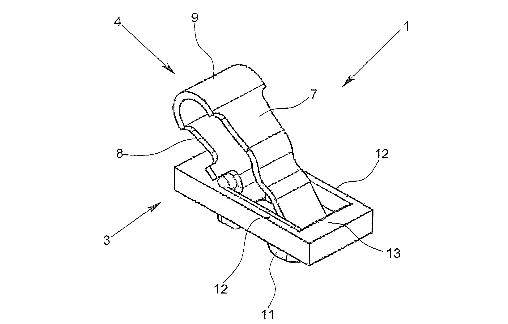
[0036]FIGS. 1 to 4 and 5 to 7 show two different exemplary embodiments of an electrical connection device 1 in accordance with the invention for connecting at least one stripped conductor end 2 or one bus bar piece 3 in accordance with the invention, only FIG. 4 showing the connection device 1 with inserted conductor end 2.

[0037]The electrical connection device 1, in addition to the bus bar piece 3, has another clamping spring 4 which acts as a compression spring on the conductor end 2 and which is inserted in the conductor through opening 5 which is made in the bus bar piece 3. On one narrow side, the roughly rectangular conductor through opening 5 is adjoined by a contact section 6 which is formed from the material of the bus bar piece 3 by a shearing and deep drawing process and extends in the conductor through direction D (FIG. 4). The roughly U-shaped clamping spring 4 has a clamping leg 7, an attachment leg 8 and a roughly U-shaped arch 9 which connects the clamping leg 7 and ...


PUM


Abstract

An electrical connection device for connecting at least one stripped conductor end, having a bus bar piece and a clamping spring which compresses an insert conductor end, the bus bar piece having a conductor through opening and a contact section which borders the conductor through opening and extends in the conductor through direction, the clamping spring forming a spring force clamping connection for the electrical conductor. The bus bar piece of the connection device requires less material use since the contact section has two side walls which extend in the longitudinal direction of the bus bar piece, are connected integrally to the bus bar piece and the contact section, and the side walls have a maximum extension in the longitudinal direction of the bus bar piece which is smaller than the longitudinal extension of the conductor through opening.

Description

BACKGROUND OF THE INVENTION[0001]1. Field of the Invention[0002]The invention relates to an electrical connection device for connecting at least one stripped conductor end, with a bus bar piece and with a clamping spring which acts as a compression spring on the conductor end, the bus bar piece having a conductor through opening and a contact section which borders the conductor through opening and extends in the conductor through direction, the clamping spring having a clamping leg, an attachment leg and a roughly U-shaped sheet which connects the contact leg and the attachment leg, and the contact section together with the free end of the clamping leg forming a spring force clamping connection for the electrical conductor which is to be connected. In addition, the invention also relates to a bus bar piece with a conductor through opening and an angled contact section for use in an electrical connection device as well as an electrical terminal with a housing and with at least one el...

Claims


Application Information

Patent Timeline
Patent Type & Authority Applications(United States)
IPC IPC(8): H01R11/22H01R9/26
CPCH01R4/4818H01R4/48185
Inventor REIBKE, HEINZ
Owner PHOENIX CONTACT GMBH & CO KG
Why Eureka
Try Eureka